Hi Andrew T, that means it is powered (so more complexity and another power supply) and it will need to be high quality/low noise (especially to drive 3mtrs to your amps)... interesting ")
But, this is not necessary if the interconnect and receiver have capacitance... what is low capacitance for an interconnect and low capacitance for a receiver/amplifier... thanks
But, this is not necessary if the interconnect and receiver have capacitance... what is low capacitance for an interconnect and low capacitance for a receiver/amplifier... thanks
Last edited:
Hi Andrew T, it took me a whole day or two to read the TGM7 and TGM8 threads... so no and I did not know they existed (and I am new to diyAudio), but please direct me to the threads with links and I will have a read. It sounds like low capacitance isn't simply low capacitance... thanks
Last edited:
Hi all, PauloPT posted the above on the TGM7 thread and I thought that you would all be interested in perusing and trying...Hi PingPing,
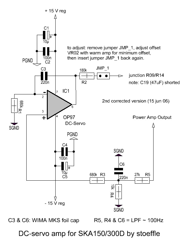
See the attached pic. This was posted long ago in an SKA thread but I can't find it. Luckily I had downloaded the pic at the time.
I have a BlackGate FK in the NFB and it sounds pretty good. But, with the amp DC coupled there is more detail, more bass extension and the music notes have a more prolonged decay. I note this particularly with piano notes.
It's not a night and day difference but that extra refinement is there.
Please do not try to DC couple the amp without a servo. You could damage your speakers!
Greg has a servo kit made for the SKA, you may want to drop a visit at his site - SKA sponsored Audio Forum - Products
Good luck with your build!
Here is PauloPT's post with a thumbnail pic of the circuit. It does not show properly in the quote (for some reason)... http://www.diyaudio.com/forums/solid-state/239418-tgm7-amplifier-based-greg-ball-ska-19.html#post3890970
Bypass decoupling caps?
Hi guys,
I need some advice: Should I bypass the 330uF decoupling electros with some film cap? If so, wich would be the recommended value for the bypass?
As I see it the purpose of the small film cap across the eletro would be to kill the inductance from the PSU leads to the amp. Also to help high frequencies.
I know AndrewT doesn't like bypasses at all, and following his advice I removed all the bypasses I had in my PSU. Now my PSU only has eletrolytic caps, no films, no ceramics, no small value capacitors! But here we are talking about decoupling caps at the amp board near the output mosfets, not in the PSU. And we are talking about minimizing the efects of wires inductance.
Other thought I had was to use very low impedance decoupling electros, like Panasonic FR or computer grade caps. Would this be advisable?
Thanks for the help.
Member
Joined 2009
Paid Member
With good bypass caps close to the pins & ground of the power FETs it becomes less critical to worry about the inductance of the wiring between the power supply and the board - just keep the wires as short as possible.
The problem with adding film bypass caps is that they can make things worse when they resonate with the parasitic wiring inductance to produce overshoot on the supply. I've never seen this happen myself but that's one of the issues I've read about. Also, the use of good quality electrolytics is usually more than adequate to achieve a good result without bypass caps. And therefore, simply putting in film caps in parallel can end up making no difference at all, or even making it slightly worse. In my own experiments I found that bypass caps on the supply lines made no difference whatsoever.
You can use capacitors with high ESR that don't 'ring' such as lower quality ceramics. Or you can use resistors in series with the bypass caps, to make a kind of zobel across the rails or around the FETs. This is what I did in my TGM7 amplifier.
However, if you are really trying to fine tune for sonics, realizing that the signal current must also flow through the power supply, then you will want good quality capacitors on the power rails near the output stage. Elna Simlic, Nichicon MUSE - are good choices in my opinion. And you can try adding bypass capacitors, not necessarily film, but other types that you can choose and listen to see if there is a better result. But this takes time as you must at least ensure you have some hours on the amplifier and power supply before fine tuning it by ear.
Last edited:
Member
Joined 2009
Paid Member
Member
Joined 2009
Paid Member
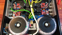
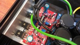
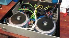
For TGM8 power supply (this amp sounds fantastic) I used two 4,700uF per rail of Cornell Dubilier (CDE) SLPX, mounted on the amplifier pcb as the main filter capacitors. These are not very expensive but they are only used as filter caps. Underneath the pcb I made bond pads for surface mount X7R ceramic bypass capacitors close to the electrolytic filter capacitor pins but I didn't need to use them. I also used Cornell parts for my TGM7 power supply which also sounds great, there I used much larger filter caps placed off-board.
For TGM8 I placed smaller electrolytics close to the output devices; these are essentially the last capacitors in the chain. For these, I used 100uF Nichicon MUSE KZ series which are their premium grade audio series. Likewise on TGM7 I placed better quality Nichicon caps right up close to the power devices.
I'm afraid that I am somewhat disinclined to spend big $ on capacitors when I get such good sound from those I have used, especially in these high feedback amplifiers. But I would be quite happy if somebody were to gift me some of those special Elna Silmic capacitors with the ceramic particles - I've read that they are the best of the bunch for large electrolytics and for an amplifier with poor PSRR where the signal current is more affected by the rail caps I might be persuaded to open my wallet a little wider.
Last edited:
I want to use 3 pairs of 9240/240 then how to change?
And if replaced by 5200/1943 is not?
Please help me, thank you very much
Hi KidDamm,
With this design you can't use bipolar outputs, only vertical mosfets.
If you want to use 3 pairs of outputs you have to change the circuit in order to provide more drive current. It's not a trivial thing, at least for me. You'll be building something closer to the GB300D which has 4 pairs.
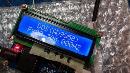
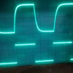
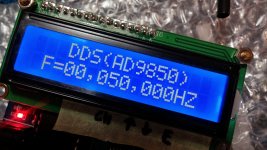
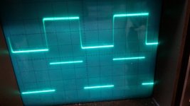
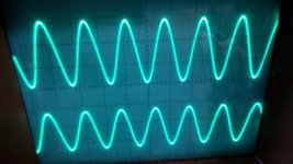
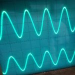
measurement
sine is good i tried to 300 khz.. square is deformed from 10 khz, any idea?
sine is good i tried to 300 khz.. square is deformed from 10 khz, any idea?
Attachments
-
 20140831_163157.jpg335.6 KB · Views: 102
 -
 20140831_16251850khz.jpg10.3 KB · Views: 106
 -
 20140831_162610.jpg250.5 KB · Views: 108
 -
 20140831_1635581khz.jpg128.2 KB · Views: 93
 -
 20140831_1632051khz.jpg148.8 KB · Views: 141
 -
 20140831_163552.jpg312.1 KB · Views: 180
 -
 20140831_162645300khz.jpg13.1 KB · Views: 84
Last edited:
- Home
- Amplifiers
- Solid State
- SKA GB150D now public domain...