I am more than happy with the 2006 topologyCorrect me if I am wrong but the SKA GB150D is a 2006 design. Greg Ball needs
an updated 2013 amp design.
") and if Greg comes out with a newer model I am on it like a hot potato...
and if Greg comes out with a newer model I am on it like a hot potato...
Lateral mosfets would be a waste in this design, which makes good use of the much lower cost vertical types.
The fets have to be regular high Vgs, not the so called logic level types.
The pairs should be matched. Splitting the 0.15R resistors into two separate 0.3R would help a little
The fets have to be regular high Vgs, not the so called logic level types.
The pairs should be matched. Splitting the 0.15R resistors into two separate 0.3R would help a little
Yes, the pairs supplied in the kit version are matched. Note the early versions didn't have the 0.15R source resistor (ie. mine doesn't). The later boards were changed to accommodate these and the larger traces required, Greg advised me.
This resitors helps to keep the bias less depended by the temperature, and also easier to set it. Another advantage, that this resistors linearize the final stage.
Sajti
Unfortunately they also drop about 1V at 7A, reducing Vgs by the same, so reducing the peak current capability. This makes the SKA even more a 8 Ohm design.This resitors helps to keep the bias less depended by the temperature, and also easier to set it. Another advantage, that this resistors linearize the final stage.
Sajti
Design is always a compromise
Unfortunately they also drop about 1V at 7A, reducing Vgs by the same, so reducing the peak current capability. This makes the SKA even more a 8 Ohm design.
Design is always a compromise
I think, that You can increase the voltage of the zeners use for protection. Even 10V version is OK, if You drive 4ohm speaker. 2pair 240/9240 should be enough for 200W/4ohm.
Sajti
The long tailed pairs clip at about 6V, with one Vbe shift down, so 6.6V is the maximum possible
Hmmmm... I don't think so. In my simulation the LTP easily push the FETs up to 10V opening voltage. This means about 450W for 2ohms load.
Sajti
2pr of 150W devices equals a total 600W of output devices.
Divide by 4 for mosFETs and the answer predicts the maximum output power that can be reliably sought as a target, i.e. 2pr = 150W
Choose the transformer to give 150W into 12ohms, or 150W into 8ohms, or 150W into 6ohms, or 150W into 4ohms.
Divide by 4 for mosFETs and the answer predicts the maximum output power that can be reliably sought as a target, i.e. 2pr = 150W
Choose the transformer to give 150W into 12ohms, or 150W into 8ohms, or 150W into 6ohms, or 150W into 4ohms.
It came from my de-rated SOAR spreadsheets when modifying Bensen's SOA sheet.
Then I worked on bjts and came up with 5 to 6 as the divisor.
These had not been mentioned previously, but I had seen many other types of recommended methods for reliable output stage modeling. They were generally coming to similar predictions, but quite a variation overall.
Cordell came along with his "interview" series. In there he uses a formula for predicting stage capability vs maximum output power.
I compared my 4, 5, 6 divisor formulae with Cordell's. The answers were almost identical.
So on that basis I still use:
Total Output stage device dissipation divided by 4 for mosFETs, or divide by 5 to 6 for BJTs.
6 suits devices with a low Vce corner, eg 1943/5200 and 5 suits devices with a higher Vce corner, eg mjl4301/4281
Last edited:
I can say without any issue at all my SKA amp drives ny speaker so far I have thrown at it..
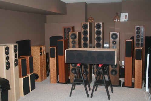
Some of the designs use a low 3.8ohm in the bottom end of the design down into the 24hz range and my amp has had no issues at all.
And I will say the photo only shows a small margin of what has been played with my SKA amp.
Some of the designs use a low 3.8ohm in the bottom end of the design down into the 24hz range and my amp has had no issues at all.
And I will say the photo only shows a small margin of what has been played with my SKA amp.
The modifications I made to my amps brought the design to 2013 standards IMO. I'm still really happy with them.
Greg added 1 resistor per rail for the source R. The .15 unit. This helps to stabilize the bias. I added a separate resistor to each mosfet. It was a pain to do but it locked the bias right in and works better then a single .15.
This amp does need matched mosfets. Matching is not that hard to do with a little thought. Greg usually has matched pairs on hand for replacements too.
Mikeg
You're right, I missed the effect of the bootstrap capacitors. This design can drive low impedances really wellHmmmm... I don't think so. In my simulation the LTP easily push the FETs up to 10V opening voltage. This means about 450W for 2ohms load.
Sajti
It came from my de-rated SOAR spreadsheets when modifying Bensen's SOA sheet....
Thanks Andrew, excellent.
- Home
- Amplifiers
- Solid State
- SKA GB150D now public domain...