post6 does not show any output device source resistors.
I'm sorry, I misspoke, they share a drain resistor, but still, they don't each have their own drain resistor so that is what I understood to require them to be closely matched. As to that. I think I bought 10 each of the P and N channel MOSFET's from Mouser and was able to make 5 matched pairs of each. They were all pretty close.
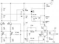
I find it difficult to read pic in 495, but I think I can see a common Drain Fuse.
I think I can also see a common Source Resistor.
Is that Source resistor fitted to your version of the amplifier?
The standard 150 does not have a source resistor, even though some Members are arguing that point.
I think I can also see a common Source Resistor.
Is that Source resistor fitted to your version of the amplifier?
The standard 150 does not have a source resistor, even though some Members are arguing that point.
I find it difficult to read pic in 495, but I think I can see a common Drain Fuse.
I think I can also see a common Source Resistor.
Is that Source resistor fitted to your version of the amplifier?
The standard 150 does not have a source resistor, even though some Members are arguing that point.
Hi Andrew,
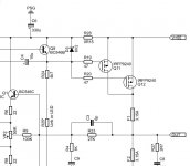
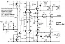
Your question caused me to look further. You are correct. I hadn't noticed that difference before but if you look at the attachments you will see in the first one, (Jim's Audio) There is a source resistor (R28), but in the second, (Greg Ball's), R28 is in line with the front end and not the output source.
Attachments
Member
Joined 2009
Paid Member
We have already discuss this some threads ago. It's not a typo, it's Jim's Audio implementation. He was asked about this and confirmed the alteration.I hope that 2nd one is a typo or else Jim's Audio has made a royal screwup !
No, Gareth is correct. The second picture in post 504 is a from a PDF I have that I must have downloaded at some time but it is not Greg's or Jim's. Whoever designed that one has the rails on the wrong side of R28. The only difference between Jim's design is that the zener connects between r28 and the source and Greg's is on the other of R28. Seems to work fine both ways.
 I had better delete it from my folder so I don't share it again.
Hi GregErskine, can you post the correct schematic? thanks...
From Post #31
Attachments
Last edited:
But there is no 0r15 Source Resistor.The .15 resistors help, a lot, to stabilize the bias.
It cannot help stabilise bias when it is not there !
which end is V+ & V- supplied from?Sorry, I don't know where I got that. Maybe an old version. The one attached shows the updated schematic that Greg released to public domain. It still shows the source resistors being shared.
The original PCB had the supplies right in beside the output devices. The layout very well attended to low loop area.
Feeding V+ & V- in from the wrong end breaks that rule. It is not the way he laid out the original PCB.
Is the resistor on your PCB fitted between the supply and the output devices.
This is the same question I have been asking.
I have looked.Please refer to posts #28 and #31. We resolved all this nearly 500 posts ago.
Post28 has no sch.
post31 shows the supplies at the other end of the supply rails.
Which is correct?
Shared Source resistor = 0r15?
or
RC smoothing for the front end, using R28&29 with C6&7?
Last edited:
Rubbish.As the schematic from post 31 and 512 is drawn, there is a shared 0.15 source resistor. I would say that the schematic is electrically correct and reflects the PCB, but it's not drawn in a way that highlights the best practice layout that the PCB may follow.
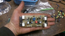
I just went up and dismantled the 150 so that I could access the underside of the PCB.
The V+ trace is directly connected to the nearest Source Pin and via a short trace to the further Source Pin. The V- is similar, just slightly longer traces due to the S Pin being on the other side of the device.
There is clearly no Source Resistor.
As a double check, I measured the resistance from V- to Source Pin and it reads 0.14r just exactly the same as the shorted probes reads.
Your GB150D pcb is old. The newer ones that Greg offers do have 0.15R source resistors.Rubbish.
I just went up and dismantled the 150 so that I could access the underside of the PCB.
The V+ trace is directly connected to the nearest Source Pin and via a short trace to the further Source Pin. The V- is similar, just slightly longer traces due to the S Pin being on the other side of the device.
There is clearly no Source Resistor.
As a double check, I measured the resistance from V- to Source Pin and it reads 0.14r just exactly the same as the shorted probes reads.
- Home
- Amplifiers
- Solid State
- SKA GB150D now public domain...