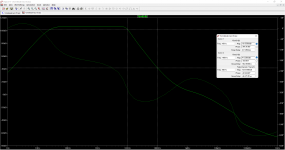
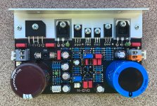
I never saw 3P compensated amplifier so I tried to build one. The basic design is come from the local forum's guru, Danhard. I made fine-tuning to adapt it to the real conditions. Three boards were built, the biggest problem was the correct placement of components and routing so as not to cause distortion degradation. The measured 1kHz/4R thd is under 0.0001%, the 10kHz/4R is about 0.0005%.

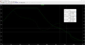
As you can seen the loopgain slope falls 60db/decade View attachment 1044059

As you can seen the loopgain slope falls 60db/decade View attachment 1044059
Attachments
Last edited:


Thanks, LKA!
I recall building something with a similar single-transistor input stage, from Popular Electronics, circa 1970. I believe that design came from an RCA app note. I've no idea re its distortion performance. This amp is way more impressive.
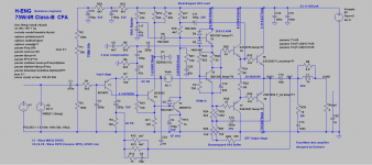
I see the 3rd order compensation network. Do you have a copy of the original schematic, or a Link? I'm curious about other compensation subtleties as well.
Again, impressive work!
Many thanks,
Steve
I recall building something with a similar single-transistor input stage, from Popular Electronics, circa 1970. I believe that design came from an RCA app note. I've no idea re its distortion performance. This amp is way more impressive.
I see the 3rd order compensation network. Do you have a copy of the original schematic, or a Link? I'm curious about other compensation subtleties as well.
Again, impressive work!
Many thanks,
Steve
Member
Joined 2009
Paid Member

THX
When I wrote "basic design" I did not mean the "root design". I don't know the origin of the circuit, but these are similar
https://sound-au.com/project217.htm
https://www.diyaudio.com/community/threads/retro-amp-50w-single-supply.236256/
I am preparing a pcb for a 60-75V power supply, which also includes an output coil. This board will be available, gerber or bare , I haven't decided yet.
I see you are using simple voltage probe to simulate Loop Gain, better to use Tian probe it will give you more accurate result.I never saw 3P compensated amplifier so I tried to build one. The basic design is come from the local forum's guru, Danhard. I made fine-tuning to adapt it to the real conditions. Three boards were built, the biggest problem was the correct placement of components and routing so as not to cause distortion degradation. The measured 1kHz/4R thd is under 0.0001%, the 10kHz/4R is about 0.0005%.
As you can seen the loopgain slope falls 60db/decade
If you prefer simple voltage probe try to plot -V(out)/v(b), it simpler to read the phase margin.
The presented loopgain captures the EF output at a quiescent current of 80 mA (linear region). BTW, the circuit can operate in AB mode with emitter resistors 0.1R-0.15R. (the main goal was not to use emitter resistors). This is the second version of the PCB, assemled with those resistors. (for testing and proving the AB mode)
Attachments
- Home
- Amplifiers
- Solid State
- Single supply, three-pole compensated class-B retro amp