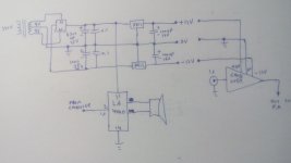
I am using this one:

if you are using this schematic with my low pass filter don't use the input capacitor C1 (short it) and increase R1 to 1K
I don't see what you mean, the output of the filter connects to the amplifier input and ground, how does the supply figure?
If you use a dual supply filter, use supply gnd for vcc-, and pin 14 as new ground for the filter.
Do you mean use the same power supply? Ground is pin 14
Attachments
if you are using this schematic with my low pass filter don't use the input capacitor C1 (short it) and increase R1 to 1K
I will do that, Thank you so much for your all out support and advice.
")
- Status
- This old topic is closed. If you want to reopen this topic, contact a moderator using the "Report Post" button.
- Home
- Loudspeakers
- Subwoofers
- single supply subwoofer low pass filter design