Hi guys, I am trying to understand how to design a single stage class A audio amp. So far I've come across the following links:
Class A Amplifier - Class-A Transistor Amplifier Tutorial
Common Emitter Amplifier and Transistor Amplifiers
The values I'm getting don't seem right at all and I feel like I am wasting my time.
The transistor I plan on experimenting with is the TIP142 and a 15V supply.
http://www.mouser.com/ds/2/389/CD00000914-249544.pdf
Will someone please point me in the right direction for information to help me find the resistor values?
You could try starting out with a simpler single stage classA amp - a classA buffer. That is - only current amplification, unity gain voltage. This is a lot easier to grasp than an amp with voltage gain too. You could use opamps if you need additional voltage gain. You'll need two power transistors - one for the buffer and the other for a constant current source load.
I am trying to drive a 4 or 8 ohm speaker load. The power to the speaker load I thought would depend on the current available from the 15V supply but if that isn't how things work then I would choose anything under 5W.
I have an adjustable voltage op amp stage that I can drive the input of the class A if that will be useful.
I have an adjustable voltage op amp stage that I can drive the input of the class A if that will be useful.
Well it should depend on the current available and also on the current that the collector load resistor allows to flow.
Maybe if you just draw out what you have and then we can take a look. You will never get a single ended stage to give 5 watts (rms ?) from a 15 volt rail and for that to be developed across 4 or 8 ohms.
Draw out what you have and then we can test it and see.
Maybe if you just draw out what you have and then we can take a look. You will never get a single ended stage to give 5 watts (rms ?) from a 15 volt rail and for that to be developed across 4 or 8 ohms.
Draw out what you have and then we can test it and see.

I'm trying to make this circuit produce as much power as possible with a TIP142 and a 15V supply.
It doesn't matter to me how much power it is able to make, I'm only trying to learn how to design for this circuit.
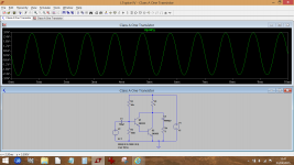
I am attaching the above file for LTSpice in case that is helpful to anyone. The datasheet link and other guides for this circuit are in post#1.
Attachments
You could try starting out with a simpler single stage classA amp - a classA buffer. That is - only current amplification, unity gain voltage. This is a lot easier to grasp than an amp with voltage gain too. You could use opamps if you need additional voltage gain. You'll need two power transistors - one for the buffer and the other for a constant current source load.
That sounds fine. Can you show me where to look to see how to find what resistor values I need to use?
Is it really that complicated to add voltage gain to it too, even in a simple circuit like this?
Hi,
The first thing to realise is a single device amplifier is a
very poor option and there is no good way to design it.
Death of Zen - A new Class-A power amp
rgds, sreten.
The first thing to realise is a single device amplifier is a
very poor option and there is no good way to design it.
Death of Zen - A new Class-A power amp
rgds, sreten.
Member
Joined 2009
Paid Member
I recommend this, from what I have read (I have not built it myself - it is on my 'list'...)
http://www.diyaudio.com/forums/pass-labs/66822-sewa-seven-watt-amplifier.html
http://www.diyaudio.com/forums/pass-labs/66822-sewa-seven-watt-amplifier.html
This is based on your circuit (two transistors to make a darlington) but look at the values... look at the 3 ohm collector load resistor. You have a couple of amps flowing in there, and all to develop a few volts across the 8 ohm load.
Huge amount of gain though. We could temper that by adding your emitter resistor but that would reduce the overall efficiency of the circuit. Also notice the output is a little asymmetrical, that's because of the large amount of 2nd harmonic distortion.
But you 'gotta start somewhere")
Huge amount of gain though. We could temper that by adding your emitter resistor but that would reduce the overall efficiency of the circuit. Also notice the output is a little asymmetrical, that's because of the large amount of 2nd harmonic distortion.
But you 'gotta start somewhere
Attachments
That much I understand. You have to start somewhere though right?
And it doesn't get any simpler than this circuit so it's a start.
Hi,
Analysis of the circuit is very straightforward as a very simple line stage.
Its not good, and even worse when applied to power amplifiers.
Get a decent book and try modelling it with (free) TinaTi.
rgds, sreten.
Thanks for doing that Mooly, totally forgot to put the darlington in there. Boy were the values I was getting wrong by using the tutorial links that I posted.
So I'm getting the feeling so far that there is no online resource that explains how to get the R values for this circuit. What book do I need to get then? Douglas Self's?
So I'm getting the feeling so far that there is no online resource that explains how to get the R values for this circuit. What book do I need to get then? Douglas Self's?
So I'm getting the feeling so far that there is no online
resource that explains how to get the R values for this circuit.
Hi,
No. Its just you being lazy and wanting to be spoon fed.
Its easy to analyse and ascertain its a very poor power
amplifier. There are no good R values, though the R
values that will work are obvious from any analysis.
rgds, sreten.
Hi,
No. Its just you being lazy.
You forgot about stupid and ugly too.
What do you mean by analyze, punch random numbers into Spice?
Hi,
If you can't analyse a 1 transistor circuit then that is your problem.
You won't learn anything from building a poor one transistor amplifier.
Get a good book, like Art of Electronics by Horowitz and Hill.
You can find the next last issue on the net as a pdf.
rgds, sreten.
If you can't analyse a 1 transistor circuit then that is your problem.
You won't learn anything from building a poor one transistor amplifier.
Get a good book, like Art of Electronics by Horowitz and Hill.
You can find the next last issue on the net as a pdf.
rgds, sreten.
Last edited:
If you can't analyse a 1 transistor circuit then that is your problem.
You won't learn anything from building a one transistor amplifier.
rgds, sreten.
I know, that IS my problem! I won't learn anything by building any project that someone simply hands me numbers for. I'm looking for a guide to calculate what values things should be like the links I posted in the OP except something that is useful. I'm not asking anyone to do the work for me, I just can't find the information online to learn from so don't get all pi$$y about it.
That sounds fine. Can you show me where to look to see how to find what resistor values I need to use?
First - define your load impedance. This is important because it determines the standing current in the EF (emitter follower).
You say you want maximum output from a 15V supply - so are you willing to go balanced (aka bridged)? This means doubling the output swing, so four times as much power is available.
Whether something is 'complicated' depends on the experience/expertise of the practioner. It looks to me from your questions that it'll be complicated for you, for experienced analog designers just a walk in the park.Is it really that complicated to add voltage gain to it too, even in a simple circuit like this?
So choose a load impedance and decide single-ended or bridged and we can get started.
You will never get a single ended stage to give 5 watts (rms ?) from a 15 volt rail and for that to be developed across 4 or 8 ohms.
Just to be picky and contrary - you could, with an inductor-fed single ended amp. Not real easy, but feasible. I have one that does a clean 8W into 4 ohms from a 13.6V supply. Pretty sure I could get to 5W at 8 ohms with the additional 1.4VDC...
First - define your load impedance.
You say you want maximum output from a 15V supply - so are you willing to go balanced (aka bridged)? This means doubling the output swing, so four times as much power is available.
OK Abrax, 4 ohms and no bridged.
- Status
- This old topic is closed. If you want to reopen this topic, contact a moderator using the "Report Post" button.
- Home
- Amplifiers
- Solid State
- Single stage class A calculations...