His mind is : " It's not product , only him in the world, And the sound is the difference between the VMOS and the VFET in NFB AMP. "
His mean is ,not "his mind"
my english si very poor
Because no negative feedback loop circuit, using a different MOS tube out of the sound is different. In addition, this circuit is my own DIY, not manufacturers.
His mind is : " It's not product , only him in the world, And the sound is the difference between the VMOS and the VFET in NFB AMP. "
Thank you for your replies and clarifying in this matter
for me it would be interesting to know more about the differences in sound character by using of the good known IFFP 9240 or an other enhanced P-CH MOSFET. Are there really advantages in such a single ended power stage by use of this rare and expensive SONY V-FET instead enhanced MOSFET's?
.html[/url]
The Vfets advantages can be summarized in less distortion which is a strong advantage when the output stage is also configured with voltage gain, as normally happens in a single ended.

The choice is even more appropriate if you choose to make an amp with no negative feedback
With regard to the sound character of Vfets I can say that moving from Vertical mos to the Lateral mos and from this last to Vfet the sound became less harsh with medium and high more refined and extended.
Following the same path (vertical, lateral, Vfets), I can say that with regard to the bass freq. the sound tends to become a little bit slower and a little less authoritative.
But considering the advantages and disadvantages, for me there is no doubt that except in the case of multiamplified systems, vfets are the best components to achieve full-range amplifiers.

Happy New Year
 Francesco
The Vfets advantages can be summarized in less distortion which is a strong advantage when the output stage is also configured with voltage gain, as normally happens in a single ended.
The choice is even more appropriate if you choose to make an amp with no negative feedback
With regard to the sound character of Vfets I can say that moving from Vertical mos to the Lateral mos and from this last to Vfet the sound became less harsh with medium and high more refined and extended.
I have the Sony parts and also some custom high current
SITs which are similar, and I think your observations are
pretty correct.
With regard to the sound character of Vfets I can say that moving from Vertical mos to the Lateral mos and from this last to Vfet the sound became less harsh with medium and high more refined and extended.
Following the same path (vertical, lateral, Vfets), I can say that with regard to the bass freq. the sound tends to become a little bit slower and a little less authoritative.
But considering the advantages and disadvantages, for me there is no doubt that except in the case of multiamplified systems, vfets are the best components to achieve full-range amplifiers. Francesco
Interesting observations, but what this is related with? I expected it is simply a matter of different transcondactance and, hence, different output impedances. In this relation, I doubt that vfets are good for No NFB full-range amps. They would fit schematics with output transformer, like proposed here by topicstarter, or schematics with reasonable NFB (Yamaha B2), or in preamps (I use power vfets in cascoded SRPP in my preamp, +100V shunt power supply, 160 mA bias, sounds really good).
Last edited:
The Vfets advantages can be summarized in less distortion which is a strong advantage when the output stage is also configured with voltage gain, as normally happens in a single ended.
The choice is even more appropriate if you choose to make an amp with no negative feedback
With regard to the sound character of Vfets I can say that moving from Vertical mos to the Lateral mos and from this last to Vfet the sound became less harsh with medium and high more refined and extended.
Following the same path (vertical, lateral, Vfets), I can say that with regard to the bass freq. the sound tends to become a little bit slower and a little less authoritative.
But considering the advantages and disadvantages, for me there is no doubt that except in the case of multiamplified systems, vfets are the best components to achieve full-range amplifiers.
Happy New Year
Thank you for yor impressions. Because both V-FETs from SONY and Yamaha and SIT's from TOKIN are very hard to find devices for most of us, the actually question for me is follow:I have the Sony parts and also some custom high current
SITs which are similar, and I think your observations are
pretty correct.
Which circuit topology reach the same (or at least similar) sonic results with currently available Power HEX-FETs like IRF series than vintage V-FETs. I guess only current buffer stages (instead stages with current and voltage gain) allow similar sound quality, no matter whether single-ended or CSPP/PPP resp. Circlomos (totem pole topology). Absolutely to avoid must be the good known "true complementary" PP stages (i. e. P-CH and N-CH), especially if the output stages don't run in pure class A, because this therm is a lie in real life and shall vote only on the schematic drawing for the eyes.
The vast majority of currently professional designers for audio power amps understand that fact unfortunately never.
Last edited:
there are variable and vertikale mosfet's:What is the difference between
Vertical mosFET and VFET?
3 VFET Acronym/Abbreviation Meanings - What Does VFET Stand For?
the abbrevation is for both VFET or V-FET, but only the term "Vertikal" stands for the internal structure.
Sony V-FETs similar to
static induction transistor types - go to
http://www.patents.com/semiconductor-device-manufacturing-same-7417284.html
http://books.google.de/books?id=hMQ...onepage&q=patents Prof. Nishizawa SIT&f=false
http://audiokarma.org/forums/showthread.php?p=564413
Last edited:
What is the difference between
Vertical mosFET and VFET?
VFET or SIT stands for a class of transistors, which's output (drain current vs ds-voltage at various gate voltages) curves amasingly resemble those of tube triodes. Even their gate design resembles tube's grid.
What is good for me from such an output curves? One is, that low output impedance is due to internal conductivity of a transistor, instead of being totally emulated by NFB in case of MOSFET.
<<What is the difference between Vertical mosFET and VFET?>>
Both are vertical (by internal structure design) FETs. The V-FETs (if attributed to
the proper devices) are related to the vertical JFETs (versus vertical MOSFETs),
and came into use in the early '70s, when there were no power MOSFETs (vertical
or lateral) developed yet. So, "they" didn't see the need to include letter J in the abbreviation.
Nowadays, we need to make sure, that we use proper abbreviations for each class to avoid any confusion.
So, V-JFET=SIT (IF the latter are made by the same design).
V-MOS are your garden variety typical switching MOSFETs (from practically all major semis manufacturer) and 2SK1529-30 audio types.
Then there are L-MOS (from a few), which, actually, were developed before V-MOS.
All the typical small signal JFETs out there (like Toshiba's and the rest) are lateral (horizontal) JFETs.
This confusion with "V-FETs" have found it's place in a few books on audio design (in the "historical chapters"), so a "critical" reading will be necessary.
Both are vertical (by internal structure design) FETs. The V-FETs (if attributed to
the proper devices) are related to the vertical JFETs (versus vertical MOSFETs),
and came into use in the early '70s, when there were no power MOSFETs (vertical
or lateral) developed yet. So, "they" didn't see the need to include letter J in the abbreviation.
Nowadays, we need to make sure, that we use proper abbreviations for each class to avoid any confusion.
So, V-JFET=SIT (IF the latter are made by the same design
). V-MOS are your garden variety typical switching MOSFETs (from practically all major semis manufacturer) and 2SK1529-30 audio types.
Then there are L-MOS (from a few), which, actually, were developed before V-MOS.
All the typical small signal JFETs out there (like Toshiba's and the rest) are lateral (horizontal) JFETs.
This confusion with "V-FETs" have found it's place in a few books on audio design (in the "historical chapters"), so a "critical" reading will be necessary.
To make a useful service to all who are interested in that type of components (v-fet, sit, power j-fet), comparing their characteristics to use these at the best, i have prepared the following page:
AMPLIMOS one stage amplifiers amplificatori audio monostadio
On this occasion, thank you in advance who will give me more or better documentation (Datasheets) for these categories of audio devices, so i can put on website.
Francesco
AMPLIMOS one stage amplifiers amplificatori audio monostadio
On this occasion, thank you in advance who will give me more or better documentation (Datasheets) for these categories of audio devices, so i can put on website.
Francesco
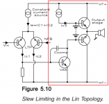
The vast majority of amplifiers (including those described in the books of Douglas Self and Bob Cordell) are made according to the Lin structure (Fig. 01). However, the disadvantage of such amplifiers is a large signal propagation delay time (from 200 ns to 1.5 μs), which leads to poor microdynamics, lifeless sound without emotions.
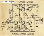
At the beginning of the development of circuitry, simple single-stage amplifiers were popular, the prototype is fig. 02. It should be noted that they sounded quite good. The disadvantage of the vast majority of class AB amplifiers is large crossover distortion. The main reason is the same - poor speed parameters.
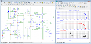
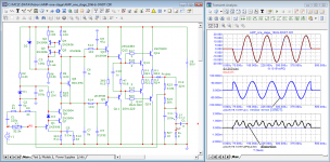
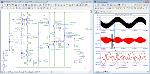
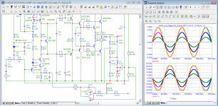
Let's build a model of a single-stage amplifier, taking into account the recommendations of Mati Otala, John Curl, Nelson Pass and other progressive authors, and measure some parameters. The voltage amplifier is made cascode, the load is a cascode current generator. The output stage is made in the form of a typical Darlington triple with paired output transistors and has no special features. The quiescent current per output transistor is 100 + -10 mA.
The amplifier is covered by two NFB circuits (R25 - is responsible for the midpoint at the output, R26 - NFB after the output capacitor - reduces the distortion it introduces). When working on a reactive load, an output inductance of 0.1 μH or more is sufficient. Suffice it to say that the linear inductance of a conductor with a diameter of 1 mm is 1.5 μH. Thus even 10 cm will have an inductance of 0.15 uH. Therefore, in a real amplifier, the inductance L1 may be absent.
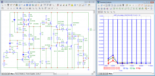
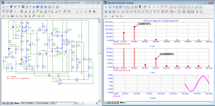
The simulation result showed that the мodel has good speed parameters (the signal propagation delay time is about 50 ns, the normalized output voltage slew rate is 1.9 1/µs). Due to this, high-speed and crossover distortions are completely absent, intermodulation products in the audio band are below -120 dB. The distortion spectrum is decreasing, the distortion products above the third harmonic are negligible.
The power supply of the amplifier can be in the range from 30 to 80 volts.
At the beginning of the development of circuitry, simple single-stage amplifiers were popular, the prototype is fig. 02. It should be noted that they sounded quite good. The disadvantage of the vast majority of class AB amplifiers is large crossover distortion. The main reason is the same - poor speed parameters.
Let's build a model of a single-stage amplifier, taking into account the recommendations of Mati Otala, John Curl, Nelson Pass and other progressive authors, and measure some parameters. The voltage amplifier is made cascode, the load is a cascode current generator. The output stage is made in the form of a typical Darlington triple with paired output transistors and has no special features. The quiescent current per output transistor is 100 + -10 mA.
The amplifier is covered by two NFB circuits (R25 - is responsible for the midpoint at the output, R26 - NFB after the output capacitor - reduces the distortion it introduces). When working on a reactive load, an output inductance of 0.1 μH or more is sufficient. Suffice it to say that the linear inductance of a conductor with a diameter of 1 mm is 1.5 μH. Thus even 10 cm will have an inductance of 0.15 uH. Therefore, in a real amplifier, the inductance L1 may be absent.
The simulation result showed that the мodel has good speed parameters (the signal propagation delay time is about 50 ns, the normalized output voltage slew rate is 1.9 1/µs). Due to this, high-speed and crossover distortions are completely absent, intermodulation products in the audio band are below -120 dB. The distortion spectrum is decreasing, the distortion products above the third harmonic are negligible.
The power supply of the amplifier can be in the range from 30 to 80 volts.
Attachments
-
 01_Lin-Topology_Ben_Duncan.png35.8 KB · Views: 117
 -
 02_prototip_Radio1970-02.png234.1 KB · Views: 118
 -
 03_AMP-one-stage_Bode.png79.3 KB · Views: 109
 -
 04_AMP-one-stage_10kHz-dist_RL-variable.png80.3 KB · Views: 108
 -
 05_AMP-one-stage_10kHz-SWDT.png39.4 KB · Views: 94
 -
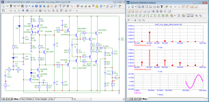 06_AMP-one-stage_20kHz-spectr.png78.8 KB · Views: 93
 -
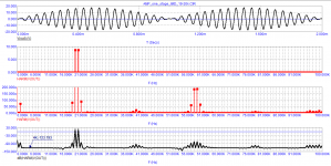 07_AMP-one-stage_IMD_19-20kHz.png28.5 KB · Views: 108
 -
 08_AMP-one-stage_SR.png79.7 KB · Views: 83
 -
 09_AMP-one-stage_cross-dist.png92.2 KB · Views: 86
 -
 10_AMP-one-stage_500kHz.png79.2 KB · Views: 80
 -
 11_AMP-one-stage_20kHz-cliping.png80.8 KB · Views: 93
 -
 12_AMP-one-stage_1kHz-FCD.png76.6 KB · Views: 111
servo control system ensures operability at supply voltage within 30...90 volts
The input capacitor operates at a polarization voltage of 2.2 volts. Since the amplifier is inverting, the AC voltage across it is practically zero (virtual ground input).
The input capacitor operates at a polarization voltage of 2.2 volts. Since the amplifier is inverting, the AC voltage across it is practically zero (virtual ground input).
Attachments
Last edited:
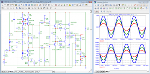
If you use a potentiometer with a linear characteristic (X4 = 20 kOhm) as a volume control, then the control becomes logarithmic. With a decrease in volume, the depth of negative feedback increases and distortion decreases even more, as can be seen at the first watt.
Attachments
It is arguable that a triple darlington is three stages, each
amplifying the current and driving the next stage. If the
technical community wants to call a darlington a single-stage,
then I have lots more single-stage amplifiers than I thought.
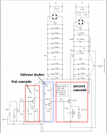
Personally, I count the number of stages in an amplifier by the number of voltage amplification stages. In some amplifiers, the output stages are in the form of a Darlington triple with 10 paired output transistors. For me, this does not mean that I have to add 12 more stages to the number of voltage amplification stages. For example, this amplifier, according to my concepts, is two-stage.
Attachments
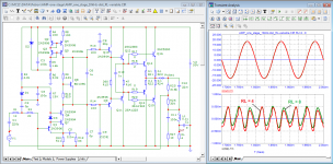
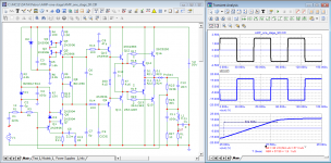
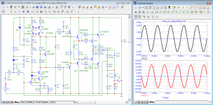
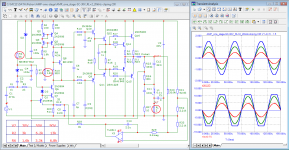
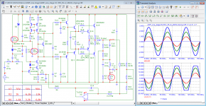
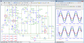
When changing the supply voltage, you should pay attention to 2 resistors, they are circled in red. The clipping mode is given at a load of 2 ohms.
Tests show the efficiency of the servo control system, the clipping voltage is symmetrical.
Tests show the efficiency of the servo control system, the clipping voltage is symmetrical.
Attachments
- Home
- Amplifiers
- Pass Labs
- Single stage amplifier