Djim,
thanks for an answer.
Wayne,
I read your reply "how I do it", but that is not how voltage sensitivity, nor power sensitivity are carried out on actual speakers.
I think and said so, back in my question that, just as Djim has confirmed, they measure Voltage and Current.
thanks for an answer.
Wayne,
I read your reply "how I do it", but that is not how voltage sensitivity, nor power sensitivity are carried out on actual speakers.
I think and said so, back in my question that, just as Djim has confirmed, they measure Voltage and Current.
Hi Oliver and Andrew,
Using an impedance chart to calculate the impedance has its limits. These impedance charts are often measured with relative small signals compared to 'normal' powering.
By measuring the Current, Voltage and frequency, all in the same time you can calculate the impedance per frequency in relation to all powering stages. This gives a much higher accuracy especially for someone who wants to measure at 100W/10m. It also shows what happens to the load when a driver comes near its Xmax.
If you prefer to measure sensitivity based on complex signals (noise for instance), measuring the current is the only way to calculate the right power values in relation to impedance.
Edit: Most DIY don't have the possibility to measure the current since their volt meters are not RMS or suited for audio measurements. In that case they have to rely on impedance charts.
Last edited:
There is no standard method of arriving at a sentitivity figure. Some use 2.83v, side-stepping power. Others use a calculated voltage, much as I've described. Even the measurement distance varies from manufacturer to manufacturer. Most scale back to 1W/1M or 2.83v/1M, but some don't even do that. The better ones at least describe their measurement process.
Interesting deviation from a HR simulation & a real world build & test here.
View attachment 261767
The Revc was actually tested & was found to be 3.55 Ohms. HR shows very close agreement @ various Impedance minima throught the FR range, without any damping")
I realise that the difference is due to damping being added, & that not all designs include it, but it does i believe highlight an area for further discussion etc.
View attachment 261767
Above is the impedance response of the stuffed system. The peaks and dips are a bit lower than the HornResp predictions (the green line) now, and the magnitudes are significantly different - not unexpected, as the damping would cause that.
The Subwoofer DIY Page v1.1 - Projects : A "Proof of Concept" tapped pipe - introduction
The Revc was actually tested & was found to be 3.55 Ohms. HR shows very close agreement @ various Impedance minima throught the FR range, without any damping
I realise that the difference is due to damping being added, & that not all designs include it, but it does i believe highlight an area for further discussion etc.
I'm sure you could use either Re or Zmin and get the same results to several significant digits.
Hi Wayne,
From tests I have done, it would seem that the SPL will typically be about 1 dB less when Re rather than Zmin is used. One advantage of using Re is that the results are conservative, or worst case.
As a refinement, using 1.25 * Re gives results very close to those generated using Zmin.
Kind regards,
David
You mean 1.25 x Zmin?
Hi Djim,
No, I mean 1.25 x Re
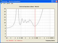
.To illustrate - for the Hornresp default record, and using Wayne's suggested method to find Zmin:
Zmin = 7.52 ohms at 905 hertz (see attachment).
1.25 x Re = 1.25 x 6 = 7.50 ohms.
The SPL curve generated using 1.25 x Re = 7.50 ohms is effectively identical to the one generated using Zmin = 7.52 ohms.
Kind regards,
David
Attachments
Last edited:
Hi David,
Sorry I meant Re, but to be honest there is no constant for the figure added to Re. Sub Horns have sometimes no more than 0.01 Ohm added.
But I'll give you a clue what I am looking for. There seems to be a relation between particle velocity (in the horn throat) and the figure added to Re (result of air resistance?)
The higher the particle velocity, the higher the figure added to Re.
Maybe that helps.
(but know I really need to look for my bed...
Sorry I meant Re, but to be honest there is no constant for the figure added to Re. Sub Horns have sometimes no more than 0.01 Ohm added.
Hi Djim,
In that case, if the difference in predicted SPL using either Re or Zmin is only going to be a decibel or so at most, then as Wayne says, is it really worth worrying about?
As I understand it, you would like to compare different designs in Hornresp to see which has the highest sensitivity. Consistently using Re rather than Zmin for the designs being compared, should give you that information.
Kind regards,
David
You are refering to relationship between acoustic impedance and the shift in driver parameters that occurs? This changes the loading on the cone. As in stiffens up the cone. You end up with a combined shift in Cms and Vas. The effects can be measured if you can do T/S parameters under power.But I'll give you a clue what I am looking for. There seems to be a relation between particle velocity (in the horn throat) and the figure added to Re (result of air resistance?)
The higher the particle velocity, the higher the figure added to Re.
If it is of any assistance David, I can do that on something I'm working on right now.
From tests I have done, it would seem that the SPL will typically be about 1 dB less when Re rather than Zmin is used. One advantage of using Re is that the results are conservative, or worst case.
As a refinement, using 1.25 * Re gives results very close to those generated using Zmin.
As I said earlier, I'd be OK using Re instead of Zmin. The difference is usually really low, like 1%. I have never seen any measurement that showed Zmin 25% higher than Re, that's closer to Zavg.
By the way, I made a few quick searches to see if I could find any manufacturers that measured current and voltage. It's not a bad idea, but it's just not something I've seen anyone do. Most actually just use xV/M instead of xW/M. The ones that use xW/M usually either do what I do (Zmin) or they use a sort of assumed nominal impedance. As an example, Bassmaxx, Pi and Precision Devices use xW/M derived from Zmin. JBL and Beyma use xV/M.
Here are some specific statements about sensitivity measurements:
Eminence:
Sensitivity - This data represents one of the most useful specifications published for any transducer. It is a representation of the efficiency and volume you can expect from a device relative to the input power. Loudspeaker manufacturers follow different rules when obtaining this information — there is not an exact standard accepted by the industry. As a result, it is often the case that loudspeaker buyers are unable to compare ‘apples to apples’ when looking at the sensitivities of different manufacturers’ products. Eminence sensitivities are expressed as the average output across the usable frequency when applying 1W/1M into the nominal impedance. ie: 2.83V/8 ohms, 4V/16 ohms.
JBL
Sensitivity - Based upon a swept 100 Hz to 500 Hz signal, measured in half space, for an input of 2 0 V @ 4 ohms, 2 83 V @ 8 ohms or 4.0V @ 16 ohms
Precision Devices
Sensitivity is derived from the sine wave response between 60 - 450 Hz at 5W/2M using Zmin. It should be noted that not all manufacturers’ sensitivity figures are based on this AES Recommended Practice.
Beyma
Sensitivity - 2.83v @ 1m @ 2Pi space
Last edited:
Hi David,
In horns for subwoofer use there is usually very little resistance added to the Re figure. When horns are used for low mid, there is usually a much higher resistance value added to the Re Figure.
I do believe this has to do with the Particle Velocity at Zmin. When this Velocity is high at Zmin it raises the impedance value of the system. When the Particle Velocity is low at Zmin, the impedance of the system becomes near Re.
Like Mark (mwvkravchenko) mentioned, it is the relationship between acoustic impedance of the horn and the moving parts of the driver. Look at a schematic diagram of a loudspeaker. You can see that all moving parts represent a capacitance figure and a resistance figure. Together with the electrical impedance of the Voice Coil, they are forming the total impedance figure of a driver.
This figure not only changes by excursion movement, like I tried to explain in post#1423, but it is also influenced by the acoustic impedance of a horn. Therefore the relation between Particle Velocity and Zmin is not so strange, in my view.

In this diagram you can see how the 'mechanical moving parts' are influencing the electrical impedance of the voice coil.
Edit: you could also make such diagram for the horn and see how the impedance of the horn is related to 'mechanical moving parts' of a driver and therefore related to the electrical impedance of the VC. Since HornResp is a model it doesn't need to pay attention to the 'mechanical moving parts' but it already shows in the 'Electrical Impdance' (Window menu), Zmin is not always near Re. In your example it shows Zmin has a factor of 1.25 x Re as result of the acoustic impedance of the horn.
In horns for subwoofer use there is usually very little resistance added to the Re figure. When horns are used for low mid, there is usually a much higher resistance value added to the Re Figure.
I do believe this has to do with the Particle Velocity at Zmin. When this Velocity is high at Zmin it raises the impedance value of the system. When the Particle Velocity is low at Zmin, the impedance of the system becomes near Re.
Like Mark (mwvkravchenko) mentioned, it is the relationship between acoustic impedance of the horn and the moving parts of the driver. Look at a schematic diagram of a loudspeaker. You can see that all moving parts represent a capacitance figure and a resistance figure. Together with the electrical impedance of the Voice Coil, they are forming the total impedance figure of a driver.
This figure not only changes by excursion movement, like I tried to explain in post#1423, but it is also influenced by the acoustic impedance of a horn. Therefore the relation between Particle Velocity and Zmin is not so strange, in my view.
In this diagram you can see how the 'mechanical moving parts' are influencing the electrical impedance of the voice coil.
Edit: you could also make such diagram for the horn and see how the impedance of the horn is related to 'mechanical moving parts' of a driver and therefore related to the electrical impedance of the VC. Since HornResp is a model it doesn't need to pay attention to the 'mechanical moving parts' but it already shows in the 'Electrical Impdance' (Window menu), Zmin is not always near Re. In your example it shows Zmin has a factor of 1.25 x Re as result of the acoustic impedance of the horn.
Last edited:
Hi Wayne,
You are probably not releasing that even your method is based on measuring current. Your impedance charts are based on a measurement that also involves measuring current, only of a small amount. All impedance measurements use current, one way or another. There is no special audio standard needed to measure impedance because physics already covers the definition for impedance:
"A measure of the opposition to the flow of an alternating current equal to the square root of the sum of the squares of the resistance and the reactance, expressed in ohms."
About sensitivity, the reason why manufacturers use Voltage/metre for sensitivity is because it makes their figure look better. Although there is no standard that forbids such way of publishing sensitivity figures, they do have a standard that says, if they use Voltage/metre charts or related figures they also have to publish the correct impedance from the system they measured. If they don’t and refer to any standards you can bring that under the attention of the corresponding organisation.
To prevent confusion, besides JBL all your examples are from driver manufacturers and not sound system manufacturers. That means their sensitivity figures should be based on measurements from a specific enclosure type and volume that is set out by the rules of the standard they are using. That means their impedance is based on the type of enclosure they are using.
You are probably not releasing that even your method is based on measuring current. Your impedance charts are based on a measurement that also involves measuring current, only of a small amount. All impedance measurements use current, one way or another.
Of course, I realize that. All electrical measurements use two known values to find the third unknown. That's pretty fundamental.
In horns for subwoofer use there is usually very little resistance added to the Re figure. When horns are used for low mid, there is usually a much higher resistance value added to the Re Figure.
In some cases, impedance rise is simply due to voice coil inductance. But the acoustic load can also increase impedance. Either situation makes a case for using Zmin rather than Re.
I find Re to be fine for subs, but I do agree that horns that are acoustically large tend to be more efficient at the low end of their passbands, and this tends to raise Zmin. Larger midbass and midrange horns show this trend, for example. I think this is another reason to use Zmin.
From the AES2-1984 (r2003):
1.6 Nominal Input Power Level.
The nominal power level used for response tests shall be stated, and the plotted response curves shall be adjusted to that pressure produced by 1 W (a voice-coil voltage numerically equal to Zmin^½).
1.7 Minimum Impedance.
The minimum impedance (Zmin) is defined as the lowest value of the modulus of impedance which a driver presents over its rated operating frequency range. (Because of the critical nature of this measurement, the manufacturer shall specify Zmin to a stated tolerance and the voice-coil temperature at which the measurement
was made.) Normal practice is for this measurement to be made at 25 ± 5 °C.
post1437 ref AES.
That is describing the conditions for frequency response.
Do they also describe the conditions for power sensitivity measurement?
post1436
P = combinations of any two from I, V & R.
If we don't know R, then we have no choice but to use I & V.
If we guess at R, then again we must use I & V.
P=IV
That is describing the conditions for frequency response.
Do they also describe the conditions for power sensitivity measurement?
post1436
P = combinations of any two from I, V & R.
If we don't know R, then we have no choice but to use I & V.
If we guess at R, then again we must use I & V.
P=IV
Also of interest, the IEC standard (IEC60268-3) allows any impedance above the rated value, but limits the impedance below. It does not allow the rated impedance to fall below the 80 % of the nominal value at any frequency down to and including DC.Thanks Djim, Wayne and Mark - interesting stuff.
This thread shows impedance rating problems manufactures deal with:
PSW Sound Reinforcement Forums: LAB Subwoofer => Preliminary impedance data for LAB subs
- Home
- Loudspeakers
- Subwoofers
- Single sheet TH challenge