Yes 300mV RMS is usable. Up to 500mV maybe, so to get 0.5mV at the -60dB MC output. The iRiaa passive networks saturate in the HF if with much input signal. They are also usually tuned for 50Ω Zout generator source. You will notice saturation when same frequency higher level square waves corners become well rounded.

Producing higher enough AC vs their nominal spec. At least when unloaded. If after loaded it won't result to below 50V DC you will have to up the value of the RD resistors. 10Ω value at least. So to create some RC voltage drop and counter the trend. 45V-49V DC loaded is safe. Consider 50V DC loaded as max at your local mains max.
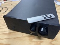
This is what happens when you finally test Ultra against as many phono pres as will show up here willing to be tested...and after building at least 8 (3 of which are amazing...but...)...yet... there are 2 decks (soon!) and 4 arms... and it's not as much fun to play with dip switches and moving cables as it is to have MORE of a GREAT thing...
...And then there's Tea-bag's "secret" Reverb shop....instant kit!
Thank you Salas (and Tea-bag).

...And then there's Tea-bag's "secret" Reverb shop....instant kit!
Thank you Salas (and Tea-bag).
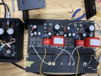
Having inserted components into incorrect places in past builds this is what I do now to help prevent that.
It's Tea's own ultra BOM and each component measured before adding to its cell, so when the build commences you don't have to keep stopping to verify a component. It is does add a bit of time but for me it is adds to the pleasure of the finished boards.
And you can download an STL file to print out your own resistor former (the white one beside the pcb) and it makes leg bending consistent and fast.
Just thought I'd share as many have shared to me in the past.
Another oneThis is what happens when you finally test Ultra against as many phono pres as will show up here
Thank you Salas (and Tea-bag).
combined with reading (of the incredible knowledge of ) Salas' threads makes it hard to withstand the itch (to build them all) — not only because its fun to do...
I had to replace the three LED's on the power side on one board. A silly mistake, I fitted J1 transistor the wrong way and when I powered up all LED's came on but one channel went out after a minute, I had two LED's left over and had to buy another from Mouser. I checked the FV of the new one and it was 1.650v and I think I remember the kit ones were ~1.850v - I now can't reach 34v output (33.8v max) from that channel with the pot at the end of its travel, and I think the new LED is slightly brighter than the already installed two.
My question is would that 0.2v lower FV on one LED be enough to prevent me achieving the 34v output - the other channel is perfect and both have 39.4v input from the Raw supply.
My question is would that 0.2v lower FV on one LED be enough to prevent me achieving the 34v output - the other channel is perfect and both have 39.4v input from the Raw supply.
Last edited:
So both CCSs run the same current (VdropR1/R1) but locally the current through the three LEDs differs (ILeds=VdropR4/R4). In "bad" channel found lower mA. Try another J1 or 100R instead of 270R R4 in the "bad".Thank you Salas,
R1 are the same but R4 is 0.514v on good channel and 0.377v on bad channel - measured a=next to LED's
All other voltages are very similar
- Home
- Source & Line
- Analogue Source
- Simplistic NJFET RIAA