Maybe a a compact size raw DC rail filter added in the phono box sitting between the umbilical and the channels DC input connectors can bring benefit beyond some passive parts details.
Of course a very balanced design between isolation performance and low output impedance is Keantoken's. Recommended for a before & after test to the handier Folded Simplistic near future builders.
Will report soon
")
the 18v TX are home... now waiting for some new perfboards.
Whatever it can be produced in the rectification or it can intrude the long power cabling.
In my prototype I could not make it catch a GSM phone buzz and I never trimmed its TPs again not noticing intermittent noises, neither a tonal nor an image shift, since I closed its lid in August. That is stock with basic PSU as it is described in the guide.
This does not mean that other builders will not aspire to more elaborate main PSUs or will not want to try some add on filter, whatever.
Freedom of personalized packaging and configuration, favorite passive parts etc. is part of the joy of building DIY audio.
Sure ! an RC network seems most logic .. LC perhaps more effective . though inductive components can easily cause problems inside the signal box
THX , Paul
No reason for expensive bulky passive filter components in the phono box IMHO. If that small Sziklai capacitance multiplier that Keantoken has tuned nicely can not cut the mustard so to perceptibly enhance PSU incoming line isolation quality then no passive can. It should reside an inch or so between the channels input DC connectors made in double mono of course.
There are two JFETs inside with their flat faces touching, its original sheet gives such pin out so its valid. That is an old TOSHIBA matched and thermally bonded pair. K369 level spec. Unobtanium or $70-100 if someone with a small stash would want to give just one pair. So you are lucky. If it is BL even luckier.
 gods seem to still be on my side .. T.G. !!
Rick, to give you a practical overview:
I use 63dB voltage gain for a Denon DL-103R 0.25mV LMC cart in my FS PCB prototype. My control preamp is configured for X1 gain (0dB). My CFA power amp for X20 gain (26dB).
My speakers are 94-95dBSPL/W sensitive. They are 8 Ohm but they dip to a 4 Ohm minimum mid-bass plateau. I drive them with the system voltage gain structure I described in 40W MOSFET class A power reserve.
The control preamp's log volume pot gives me practically same SPL either for the Benchmark DAC or the Folded Simplistic at same positions. Some records play louder than the CDs even.
At 12 o'clock I enjoy "loud" peaks at four meters from the speakers that can cover a vivid conversation. Beyond 2 o'clock its just "too loud".
The Folded simplistic has a JFET buffer output stage itself of about 50 Ohm impedance and similar design to a capacitor coupled B1.
I hope that I have given you enough example info to weigh and decide your own configurations.
I meant asking about the phono itself if p2p so to know the intention of using external regs of higher CCS or not VS the VA rating of the transformers.
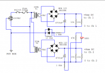
The PSU does not need a PCB. Its very basic. Its ground loop breaking scheme worked for no loops in my system. As in the guide and in the first picture here.
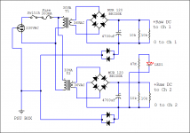
In case it does not in some other systems, then an alternative I can suggest is in the second picture. More I can not predict since the system grounding is a general matter that varies between installations and has not to do with the main phono build.
The PSU does not need a PCB. Its very basic. Its ground loop breaking scheme worked for no loops in my system. As in the guide and in the first picture here.
In case it does not in some other systems, then an alternative I can suggest is in the second picture. More I can not predict since the system grounding is a general matter that varies between installations and has not to do with the main phono build.
Attachments
- Home
- Source & Line
- Analogue Source
- Simplistic NJFET RIAA