I am puzzled... should I use 36v instead ?nicoch46 said:yes you can try ,only few resistor to change at last for 36v
I am seraching for the best sound possible.
salas said:Rcruz, what kind of input impedance does your line stage have?
It is difficult for me to say....
I am using a meridian 101 pre with a MM phono stage built in.
It also has a buffered radio input.
The other input is tape with a 10kohm before the 10k volume pot. (It´s here I want to plug your RIAA)
Can not post the schematic but will send it to your e-mail if you care to analyse it for me.
Ricardo
Don't bother, I just read its schematic. We will avoid its complex enough & dated radio buffer. We will feed through tape 10k in.
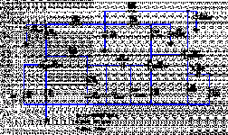
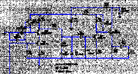
For 0.8mV you better make what I attach. Has the best gain for that.
4.1k resistors are made by 8k2//8k2. 45k from 100k//82k. The Rx is what you will find as best damping for input load for your cart in your system. Start with 1k, and see for lower. Choose by ear. This circuit has a simple Jfet buffer and will drive the 101 happily.
Use a 22V 50VA toroid, that will rectify to around 30V. Regulate for 25V. When you will make it we will be happy to see some photos here and your review. Thanks.
Attachments
RCruz said:
The other input is tape with a 10kohm before the 10k volume pot. (It´s here I want to plug your RIAA)
Can not post the schematic but will send it to your e-mail if you care to analyse it for me.
Ricardo
That input adds to 20k load. The 10k that I show in the schematic's output above is a virtual load. Just use 22k for that. The Meridian will shunt it down to nominal.
salas said:
That input adds to 20k load. The 10k that I show in the schematic's output above is a virtual load. Just use 22k for that. The Meridian will shunt it down to nominal.
Perfect
Thank you very much for your help.
I will be posting the evolutions and ask for advice.
Ricardo
anatech said:Hi Salas,
The Ortofon drives a MM input just fine, but this opens a possibility to use a preamp with no phono input.
Thank you very much Salas.
-Chris
Hi Anatech,
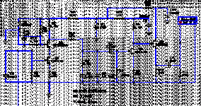
Here is a refined MM cascoded & buffered version. Make this one.
Attachments
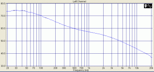
Some measurements
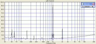
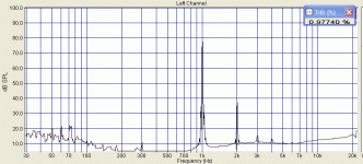
So to conclude the presentation, I guess that some measurements are in order. First is the FFT spectra and THD.
It does 0.091% THD for 2.2mV input, 220mV output on 100k load. The hiss is 80dB down. The 50 Hz hum in the particular built is 70dB down, and no 100Hz can be seen from the PSU at all. Remember that is for the 40dB 20V version for high MC. Pretty good for a non feedback SE circuit I would say. Hence the distortion is 99% 2nd harmonic.
Attachments
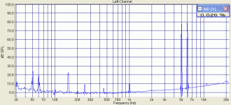
So the above FFT indicates that we may typically expect 1% THD, and 60dB dynamic range for surface noise and rumble, in a logically well sorted out set up. Not necessarily very expensive. That is for a new stylus and good tracking geometry. Also for a silent non worn out disc.
Hi guys, great thread.
Salas, I am thinking of building the version you posted above for use with a MM cartridge (a Grado Prestige Gold).
Is there a specific reason that C5 & C6 are 330uF?
Could these be safely changed to 220uF? I only ask as I have many 220uF caps I could use. I'm a bit of a noob at phono-stage design, but am willing to learn, but I think I understand the basics.
Thanks in advance,
Lee.
Thomo said:Hi guys, great thread.
Salas, I am thinking of building the version you posted above for use with a MM cartridge (a Grado Prestige Gold).
Is there a specific reason that C5 & C6 are 330uF?
Could these be safely changed to 220uF? I only ask as I have many 220uF caps I could use. I'm a bit of a noob at phono-stage design, but am willing to learn, but I think I understand the basics.
Thanks in advance,
Lee.
Hi Lee,
As I have practically completed my cascode experiments that I will soon subjectively evaluate more and present, (but for a higher sensitivity), I have modified the 36dB schematic for your requirements, including what I have learned as better in practice. The local bypass cap goes. A local current sourced stabilizer does better job than the divider, using an 8.2V 1W zener and one non matched leftover FET. You can still use the divider instead for simplicity (not the best performance), but without any shunt cap over it's lower resistor, it audibly intrudes.
P.S. The answer to your original question about the bypass cap value, is that the bigger the better. The more the dynamic PSU resistance, the bigger cap decouples lower and better. Best would be a Blackgate non polar 1000uF. But we gracefully avoid such components with the new base bias scheme.
Attachments
Hi Salassalas said:
I have modified the 36dB schematic for your requirements, including what I have learned as better in practice. The local bypass cap goes. A local current sourced stabilizer does better job than the divider, using an 8.2V 1W zener and one non matched leftover FET. You can still use the divider instead for simplicity (not the best performance), but without any shunt cap over it's lower resistor, it audibly intrudes.
I am now building a PSU for your design on post 166: http://www.diyaudio.com/forums/showthread.php?postid=1628846#post1628846
After reading your last post, I wonder if these best practices are aplicable in my case and should bring improvements ?
Sorry for the question but I still can not grasp all the concepts with ease.
Ricardo
Hi RCruz,
No, you have a different case. You have a Benz Clear high MC. The MM guys need avoid the input capacitance and need lower sensitivity. The cascode is a necessity for them. It adds more sensitivity to PSU, gets more complex, and yet has to persuade me for any sonic advantages in this kind of phono concept. You need the original circuit you aim at.
No, you have a different case. You have a Benz Clear high MC. The MM guys need avoid the input capacitance and need lower sensitivity. The cascode is a necessity for them. It adds more sensitivity to PSU, gets more complex, and yet has to persuade me for any sonic advantages in this kind of phono concept. You need the original circuit you aim at.
- Home
- Source & Line
- Analogue Source
- Simplistic NJFET RIAA
