I assume you got R1 47K load also? You did not mention.
Yes R1 and R14 are both 47K.
I think the preamp board draws about 100mA, so you will need more like 50-100R to drop 5-10V.
I see Salas beat me to it.")
How's your rare Denon model doing music lately? Still satisfied?Yes R1 and R14 are both 47K.
Looks like the DIP switch ones you had chosen will be good values for high output MC carts.

To see it cutting in real life you got to load each raw DC output with a dummy for 100mA or use the phono channels themselves to load them down.
I think the preamp board draws about 100mA, so you will need more like 50-100R to drop 5-10V.
I see Salas beat me to it.
Thank you both. Like I said I did not work much on that part. I was not sure exactly why it is higher and if that is somehow related with measurement I was getting on that one channel. Wanted first to check here with you what I am looking for to achieve, and than to deal with it. Yes thank you I am familiar with that great tool - Duncan's PS. I believed after 1 ohm I tried as well 180 ohms as that is what I had from higher values in my power resistors bin, but do not remember exactly what was measured. I know that it did not affect problem on that one channel, so I did not pay much attention to it. I left 2 wire soldered in RD/link position (in each RD/link position) so it is easy to test various values between, as I new it might need adjustment.
Thank you
AR2
Now you got the info to fix everything to spec. Let us know how it went.
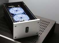
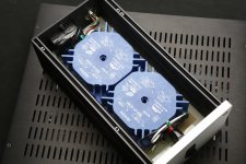
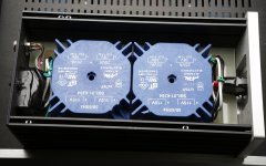
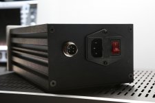
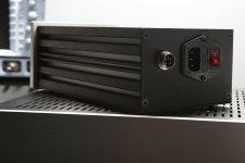
Sure. In the meantime here are some images. Power supply transformers. I etched board that fits nicely into the case to hold transformers and distribute power lines.
Attachments
Now you got the info to fix everything to spec. Let us know how it went.
OK, this did it. I used 20 ohms 10W (that is what I had) and the voltage right now at the output of DC power supply is 48 V. Than, channel that was problematic, with 11K at R3x is right now right on money 3.6V TP1-TP2 and 34V + Rail. On another hand the channel that was OK, I have max 3.3V TP1 - to TP2 and 34V max. So I guess I will change down R3x from 11K to ether 10K or 9.1 K where it was before.
Thank you for all the super fast help!
AR2
Nice photos. Very orderly transformer box build. Keep secondary AC cabling that enters the phono box well twisted and dressed, far away from any internal & external signal cabling. Especially from phono input signal route. We normally put the rectifying PCBs in the little box so to send out DC cabling that emits no hum field. But you don't have the space for such boards in that box as I see. Let us know how the rest went and how it played with your cart. Best load etc.
Its OK to keep 11K on both since they cover the TP setting range and have some spare max. You got VR2x to fix the exact voltage anyway. R3x only set the max. Each channel usually needs bit different Rail+ for same TP readings. Due to differences in the semis.
Its OK to keep 11K on both since they cover the TP setting range and have some spare max. You got VR2x to fix the exact voltage anyway. R3x only set the max. Each channel usually needs bit different Rail+ for same TP readings. Due to differences in the semis.
Nice photos. Very orderly transformer box build. Keep secondary AC cabling that enters the phono box well twisted and dressed, far away from any internal & external signal cabling. Especially from phono input signal route. We normally put the rectifying PCBs in the little box so to send out DC cabling that emits no hum field. But you don't have the space for such boards in that box as I see. Let us know how the rest went and how it played with your cart. Best load etc.
Its OK to keep 11K on both since they cover the TP setting range and have some spare max. You got VR2x to fix the exact voltage anyway. R3x only set the max. Each channel usually needs bit different Rail+ for same TP readings. Due to differences in the semis.
Really neat work on that psu AR2.... where did you get the enclosures ?
Can you post some pics of the preamp ?
Hi RCruz,
I got them here from DIYAudio store. Those are Italian made and really great in quality. I will post pictures of preamp when it is completely done. For now is in the case, but since I am still tiding it up it is not ready for the show
To answer Salas's comment - since I got these from DIYAudio store, these were the only two sizes available at the time, hence the decision to have transformers only, while PS is housed with preamps. Since all the wires are shielded and twisted than I am hopeful it will not create problems. Preamp case is pretty spacious so AC lines are far from anything else. I decided to go for these cases without waiting for new order, since I promised to my son to do this... so deadline is much tighter than when I am making something for myself, haha.
Salas thank you very much for sharing, supporting and making available such a great preamp. Both my son and I had a little time to listen and it's really exceptional sounding phono preamp. We had it plugged into tube preamp and Choky's J2 amp over Tannoy speakers. Great definition and kick *** bass. My youngster has a really nice collection, between others I found Wish You Were Here new 180g release. That record really placed shine on that diamond of your preamp.
Last edited:
In MM mode especially, chances for hum are lowest. But good dressing of anything AC in the phono box will pay back if ever decide to mod towards MC following the guide's few parts exchange. Great options exist in the high output MC carts world too and the next step 43dB gain mod serves them well without getting into the finicky and sensitive zone yet like expensive low MC carts can be. Nice to know that your first impressions are heartening. 6mV cart goes very well with the 47K or 33K loading and 40dB setting you implemented. Keeps overload and hum at bay. So far so good then. Let us know more with time.
Need to try, but I'm thinking how... Enclosure top coating is not conductive. it is some kind of grey paint. i'll figure out something in order to test it...
Thank you all for ideas and advises. I'll report accordingly and soon....
I made several tests based on your guys advises:
a. inserted MU Metal sheet to cover the motor.
b. inserted copper sheet to cover the motor.
c. connected TT GND to motor’s shell
d. connected Earth GND to motor’s shell.
Unfortunately, there is no change and I think I'll leave it as is.
Any way this noise is starts to be audible at 70% of volume level which is too high. I’m listening my TT at 30-40% max.
Would be interesting to test it with another cart, but currently I do not have any. Would be my future task if I'll find one.
One more q.
I use 6m subwoofer cable (AQ made with DBS) and sometimes my sub turns On by itself when all devices are completely off.
It has a signal sense input for turn On function...
Can't connect these events to any household accessories On/Off like fridge or AC. I assume I need to install snubber at the sub input to min RF, but it’s hard to get into the sub circuit.
Any other way?
Thank you.
Try making an RF choke with a ferrite core. Just an idea.
Best regards Ebbe
One more q.
I use 6m subwoofer cable (AQ made with DBS) and sometimes my sub turns On by itself when all devices are completely off.
It has a signal sense input for turn On function...
Can't connect these events to any household accessories On/Off like fridge or AC. I assume I need to install snubber at the sub input to min RF, but it’s hard to get into the sub circuit.
Any other way?
Thank you.
Can be ground loops. Use the same hole in the wall for all equipment or break the loop with a transformer. Or did you already have that?
Its only about when his AC motor works and taking the cartridge near the disc center that picks a bit of hum. When shutting the motor down, nada. About the Sub triggering on its own, it should be spurious noises picked. Maybe es44 has a point. Would be easy to try those clamp ferrite things we see on computer data cables sometimes.
An externally hosted image should be here but it was not working when we last tested it.
Hi Salas
I am planning to build a multiple input folded so I can have MM and MC inputs.
I need to duplicate the input stage and use the riaa filter and output stage common to both inputs.
I did not yet figure where I should put the switch to select inputs and am having doubts about C6.... I believe you explained that one should not cut power abruptly because C6 would discharge over the folded, but I can not sim it and do not really grasp the issue.
Can you please give me a hint ?
Best
Ricardo
Can be ground loops. Use the same hole in the wall for all equipment or break the loop with a transformer. Or did you already have that?
Yes, it is already there installed.
I have 1:1 isolation trany at Cable output from RepAmp->Linkwitz->Iso..Trany-> Cable....
- Home
- Source & Line
- Analogue Source
- Simplistic NJFET RIAA