On the folded, can I ask a few questions...
I'm about to buy some boards, and am realising that this is going to cost a lot and possibly be a little tricky to put together...
What is the relationship between the switched resistors Rx1 - Rx4 and R1, R2, R3 & R4 please?
In the build guide it says that the resistors R2 and R3 can be variable values, but I thought it was the Rx resistors that related to the input resistance for different cartridges. I am a little confused...I have a Shure M97xE cartridge, by the way.
Its not tricky to put together when having the right FETS already selected.
Rx1 - Rx4 are just selectable cartridge load and related to R1 only which shunts them.
R2 and R3 are not variable values but proper recommended different values regarding each sensitivity choice build and the at hand 369s IDSS.
Rx1 - Rx4 are just selectable cartridge load and related to R1 only which shunts them.
R2 and R3 are not variable values but proper recommended different values regarding each sensitivity choice build and the at hand 369s IDSS.
I'm thinking of using the first stage of the folded as a step-up for a LOMC (.12mv) into a tube phono stage. What is the voltage drop across the D/S of the 369? The reason I ask, I would like to run it off of a 24 v battery to keep the noise low. From the construction guide, if I did the math right, is it about 13 volts ?
Its not tricky to put together when having the right FETS already selected.
Rx1 - Rx4 are just selectable cartridge load and related to R1 only which shunts them.
R2 and R3 are not variable values but proper recommended different values regarding each sensitivity choice build and the at hand 369s IDSS.
Got it. Thanks. I guess what seems tricky for me is when I have to do electronics calculations, and I am out of my depth, so any variable where I'm not given a clear build guideline "buy this resistor, put it in there" makes me wary - it's not laziness, just lack of confidence. I have learnt how to test jfets for IDSS, match leds for voltage, etc etc. but it still worries me to have to learn a new trick. You've always been a star in the past, Salas, holding my hand, as it were.

I only have a matched quad set (11mA) of the 369, so may have to try pairs first and see how it goes. I do have parts to build a 36V shunt, so I guess I will give that a try, if it will be lower noise. This will have to do until I decide if I like the cartridge (DL-103m). Then redo the active and save up for a nice SUT.
Thanks Salas...and all
Thanks Salas...and all
If I only knew what HFE was
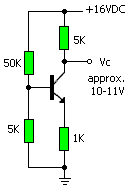
Forward current gain. You can measure it like this if you dont happen to have a DMM with hfe-measuring option. Take the two highest matching.
Attachments
Presumably measuring the IDSS of the K117GRs is the same as the K170BLs??
Same procedure sir!
I only have a matched quad set (11mA) of the 369, so may have to try pairs first and see how it goes. I do have parts to build a 36V shunt, so I guess I will give that a try, if it will be lower noise. This will have to do until I decide if I like the cartridge (DL-103m). Then redo the active and save up for a nice SUT.
Thanks Salas...and all
I would add a cap multiplier after the reg for such a pre-pre. A pair pulls 19mA plus 5mA the LEDS so ~ 50mA in stereo, so a battery will tend to drain out.
Thanks Stajo. I do have a DMM with Hfe option. How do I use it please?
Well, first set the selector to something like hfe or something. Then find the holes. It might say ECBE (Emitter Collector Base Emitter ) or maybe DSGD (Drain Source Gate Drain). Then choose if its a NPN or PNP, you find that in the data sheet. There you can also look up the pin order to see if you shall use ECB (the 3 holes to the left) or CBE (to the right).
Or simply test your way and get a reading if you dont like datasheets
")
hFE is the ratio of Emitter current to Base current.
It varies with emitter current and with frequency and with temperature.
Try to keep frequency and temperature fixed, then you only have to be concerned with selecting a suitable emitter current.
Ask here what emitter current you need to test at. It should be the current that the device will pass when in circuit.
You need a resistor in the collector lead and another resistor in the base lead.
Using the DMM to measure the voltage drop across these two resistors lets you arrive at collector and base currents. Then just divide one into the other.
There is a tiny error due to collector current and emitter current not being exactly equal. For hFE=100 the error is 1% and does not matter.
For hFE = 500, the error is ~0.2% and matters even less.
The circuit in post 13314 has omitted the base resistor. Try somewhere between 1k0 and 10k.
The collector resistor is shown as 5k. This may be too big to allow the correct emitter current to flow. Try reducing to 100r to 1k0
I prefer to set the emitter resistor to 0r0. Otherwise the Re works as Negative Feedback and swamps accurate readings of hFE.
Last edited:
So, will a match at the DMM's low current level be irrelevant when the device is in the circuit with a higher current? It's so easy to test in the DMM, and I've just done a batch of them, mostly with readings of 500-650 hFE. Are you saying, Andrew, that I should retest in a test circuit?
- Home
- Source & Line
- Analogue Source
- Simplistic NJFET RIAA