About the 30 Ohm spec of its standard buffer you are right, for BL should be ~60-70 Ohm. Looks like I had noted max spec for V type Fets that I had measured in a special build. Its an inadequate note. Should read ''under 100 Ohm with average IDSS JFETS''.
Noted.

The mains voltage here in the UK I find is often higher than 240V. The transformer primary is rated at 230V. The net result is a higher than expected DC. I have a 30Vac transformer which gives me 51V DC which is going to be too much for the LM317. I need a 28V trannie to do this right.
Hi
my shunt is not regulating. LedStringV=5.45V VgsQ1=3.6V dummy load=940R VgsQ4= ~0.001VDC??? . Need 28VDC 30mA regulated. Output is like 3VDC. No smoke") . Checked several times- wireing, schemo, parts values, all OK. Both mosfets(9240) are cool- not even warm. Any ideas?
. Checked several times- wireing, schemo, parts values, all OK. Both mosfets(9240) are cool- not even warm. Any ideas?
Cheers
my shunt is not regulating. LedStringV=5.45V VgsQ1=3.6V dummy load=940R VgsQ4= ~0.001VDC??? . Need 28VDC 30mA regulated. Output is like 3VDC. No smoke
. Checked several times- wireing, schemo, parts values, all OK. Both mosfets(9240) are cool- not even warm. Any ideas?Cheers
Chalk: Congrats for debugging it. Why wrap it in a chip pre reg anyway? Adding circuitry... keep it simple, it has its own input insulation via its CCS.
Milos: Your shunt Mosfet ain't open. Check orientation, health, 4 wires circuit to load, check if you got drop on R1.
Milos: Your shunt Mosfet ain't open. Check orientation, health, 4 wires circuit to load, check if you got drop on R1.
Orientation OK.Check orientation, health, 4 wires circuit to load, check if you got drop on R1.
Health: all parts are brand new and both channels behave the same. I doubt that something is broken. It is mainly P2P, a bit p.i.a. to check, I leave it for the end if everything else (if anything) fails.
4 wires twisted connected to the load.
R1 drop 1.5V.
I feed it with 36VDC (10000uF per a ch. filtered)
Trimmer has no function, turning it in either direction produces only slight variation in voltage output which is ~3V.
Q4 on either ch. wont open.
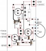
Layout attached.
Dotted lines=jumpers.
I have no idea what to look for after about 10 hours of checking and staring
Attachments
Last edited:

No, quick solder, but I just noticed after tightening MOSFETs to the HS,that they short to GND!!! I use silicon pads to insulate and heat transfer, will have to check what is going on.
I'm quiet positive that I checked for shorts before 1st switch on. There was no smoke no heat...go figure.
I'm quiet positive that I checked for shorts before 1st switch on. There was no smoke no heat...go figure.
Talking about irons, this one European mains compatible station offer just popped up in comparable pricing to US at last, just cut off the plug end and fit a Schuko.
Hakko FX-888
Hakko FX-888
Graphite pads not silicone as I wrote above. Yes, they are smooth and no rough edges or anything to prevent good heat transfer and insulation...the interface between the device and heatsink must be smooth, (not necessarily shiny).
This requires that both the device and the heatsink are flat and have no ragged edges that could cut through an insulating layer.
Both ch. are now OK. The problem was with those graphite insulation pads, not cold solder. Once I changed the insulation pads to silicone pads+silicone grease I lost all weird behavior. The circuit needs some time to stabilize (about 5-10min), after that , it is rock solid voltage. I connected the shunt to the o-scope, and it shaws perfect dc, no oscillations what so ever. Now I have to wait for some parts to come in from Parts ConneXion, than I'll do the RIAA
part.
Salas thank you very much indeed, once more.
Cheers
part.
Salas thank you very much indeed, once more.
Cheers
- Home
- Source & Line
- Analogue Source
- Simplistic NJFET RIAA