Hi,
after a lot of reading here i finally bought some 2sk170 to start building this phono preamp. After checking Idss i found the following values:
3.08, 3.53
4.07, 4.75, 4.80
5.83, 5.92
6.28, 6.30, 6.36
Can you advice me how to pair them and wich of the schematics to use ?
I have a Rega fitted iwth Ortofon OM5E and i intend to upgrade to Nagaoka Mp110.
Since few months ago i'm using a phono preamp based on the application note from LM49720 datasheet wich sounds really good.
I hope and expect this solide state to ouperform my opamp based preamp.
All the best !
I suppose they are genuine. From my info they where sourced from TME.
OK I checked some, the printing and plastic shape on yours look OK, don't know about feet because mine aren't the ''cowboy'' ones. Since they fall in the correct GR IDSS range also, lets proceed.
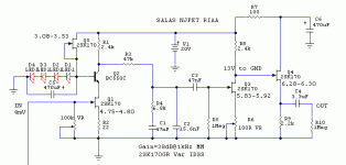
It was a juggling act to fit your various IDSS GR in a working scheme. Here it is attached. Use R6 trimmer to bring Q3 drains at about 13VDC above ground initially (all Jfet drains oriented up towards V+). The same trimmer will be handy to match the AC output between channels since no channel will have exactly same Jfets, if you got reverse riaa and generator for measurements. But transconductance ain't that far as I staggered the jfets per stage, so AC gain matching it may be satisfactory on first shot.
Use some easy 20V 317 supply at first to check it works OK, but use one of the recommended shunt regs for proper evaluation. Watch C3 quality in particular, Teflon if you can. R3,R4 quality and matching is most influential too. C1,C2 strive for precision. C4 use what you like best in line stages.
LME49720 textbook riaa preamp is not something to put under the same tonal scope, this one is more like an open loop tube phono sans heaters. It either captures your liking or not. Surely different at least. Turn VR 100K input trimmer without any additional loading capacitor when your MM cartridge is eventually hooked up and try to listen for best balance. If you can not find acceptable balance still, try 50pF load capacitor steps additionally, turn VR. Replace VR100K with good quality resistors later at settled value. Good luck, let us know.
Attachments
Salas i apreciate so much your effort of customizing the preamp for my transistors. Today or tomorrow i will etch my pcb and populate it. For the first release i will not have teflon caps but i will try some red wima.
Regarding power supply i was thinking to use some batteries.
Efharisto")
Regarding power supply i was thinking to use some batteries.
Efharisto
Batteries have no ripple but for extended very low output impedance (which this circuit appreciates due to no PSRR) it depends. Use one battery per channel bypassed by a very large electrolytic on its terminals at least. Ultimately shunt regs will not drain out and in my experience are the best long term solution for it. But to have a taste of the circuit, any decent power source first is practical.
Having just finished my Mesmerize I think that time has come to complete things with the Simplistic. From 2009 I have collected all parts but for various reasons I have not built anything yet.
In the meantime I understand that there is some evolution so I need your advice/guidance.
My cartridge is a 0,3 mv 30R Yamaha MC5. As such it falls in the gap between the Regular MC schematic (0.4 - 0.6 mV) and the Low MC pre pre (0.15 - 0.25 mV) + HiMC / MM schematic.
Which path should I follow ?
A second subject that I want your opinion is which regulator to chose. Version 1.0.5, BIB, ... ?
After much head-scratching I finally got mine working. As I soldered pin holders in for Rload (so I could easily change them to suit my cartridge), I didn't have any resistors in when testing. Unfortunately I only tried adding RLoad after I has replaced Q4 and Q5 on both channels.
I'm currently using my Supex SD900 to test and there is definitely more space and detail in the midrange and treble compared to my stage that used polystyrene RIAA caps and V1.0 regs.
I also notice that the BC550 in the CCS of the regs get hot - too hot to touch for more than a couple of seconds - is this normal?
I'm also getting more 50Hz noise that i used to with the same grounding arrangement, but that is something I can work on now. The gain seems to be pretty closely matched on both channels. As always, thanks Salas for you're help.
Last edited:
At 45VDC if the Jfet above sinks enough IDSS through the BJT in the Vref, its normal. Same for the CCS ones when having 25-30V across each depending on what you feed. Stick it a little piece of metal on hottest one with some resin if you can. Without Rload yes, the gate circuit has no reference and it kinda ''flaps in the wind'' hence the weird voltage indications before. All well then. Have you got a file as you used to post, so we can hear it?
Having just finished my Mesmerize I think that time has come to complete things with the Simplistic. From 2009 I have collected all parts but for various reasons I have not built anything yet.
In the meantime I understand that there is some evolution so I need your advice/guidance.
My cartridge is a 0,3 mv 30R Yamaha MC5. As such it falls in the gap between the Regular MC schematic (0.4 - 0.6 mV) and the Low MC pre pre (0.15 - 0.25 mV) + HiMC / MM schematic.
Which path should I follow ?
A second subject that I want your opinion is which regulator to chose. Version 1.0.5, BIB, ... ?
Pre-Pre + hiMC I would say on 330R cart load, you gonna need the gain especially with a Mez as control centre.
At 45VDC if the Jfet above sinks enough IDSS through the BJT in the Vref, its normal. Same for the CCS ones when having 25-30V across each depending on what you feed. Stick it a little piece of metal on hottest one with some resin if you can. Without Rload yes, the gate circuit has no reference and it kinda ''flaps in the wind'' hence the weird voltage indications before. All well then. Have you got a file as you used to post, so we can hear it?
Is it the 2n5457 or the 2sk170 idss that governs the bjt current? I think i used 10ma k170 to make sure I could get 45v out. what's the lowest idss i can use here?
I will try and get a needle drop recorded tonight. I want to get my hum problem sorted first
If you don't mind I will post my drain voltages to make sure they are within the design values.
2N5457 or BF245A collector load governs the BJT current. The K170 governs the Vref current and its amount is regulated by the source to ground 1k trimmer in 1.2R regulator. Lowest depends on how high a Ref resistor is used. BL range wil suffice with standard values in the schematic.
My drain voltages are:
L R
Q5: 14.6, 13.8
Q1/Q6, 5.5, 5.5
Q2 9.4, 9.6
Q3 18.9, 18.2
Q4 collector: 9.4, 8.9
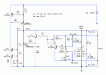
I've attached the V1.2R schematic I used as a reference, what is the best way of decreasing the current please? I used a 2K trimmer instead of a 1K, will that make a difference?
Here is a needle drop of the stage (Pink Floyd - Money), I've still not resolved the grounding issues but it is better than it was, it is currently grounded using a crocodile lead and I need to make it permanent:
Money_SalasV12r_Teflon.wav
The left channel seems to have very slightly more gain, but I need to make a lead to connect one channel from the cartridge to both channels on the phono stage to compare gain accurately.
RLoad is currently 300R, probably a bit high for the Supex but supposedly ideal for my Dynavector TKR, so the bass is tighter than it with the old stage using 100R.
L R
Q5: 14.6, 13.8
Q1/Q6, 5.5, 5.5
Q2 9.4, 9.6
Q3 18.9, 18.2
Q4 collector: 9.4, 8.9
I've attached the V1.2R schematic I used as a reference, what is the best way of decreasing the current please? I used a 2K trimmer instead of a 1K, will that make a difference?
Here is a needle drop of the stage (Pink Floyd - Money), I've still not resolved the grounding issues but it is better than it was, it is currently grounded using a crocodile lead and I need to make it permanent:
Money_SalasV12r_Teflon.wav
The left channel seems to have very slightly more gain, but I need to make a lead to connect one channel from the cartridge to both channels on the phono stage to compare gain accurately.
RLoad is currently 300R, probably a bit high for the Supex but supposedly ideal for my Dynavector TKR, so the bass is tighter than it with the old stage using 100R.
Attachments
Last edited:
Your voltages are OK. Could make do with 46V PSU also. What current you want to decrease? CCS current? That is done with R1 value. CCS=0.61/R1. 2K trimmer is fine with 10mA Q9 IDSS. 100 Ohm load for the Supex is theoretically better. But make a pass from 220 Ohm to evaluate also.
Thanks Salas, does it sound like I am missing anything, how does it compare to some of the best phono stages you have heard? When it comes to phono stages this is the best I have heard so I don't really have much of an ultimate reference. I do notice that the leading edge of drums for example are far better than with the old phono stage, it has the kick of a (very) good CD player. Seperation is much better as well as detail. I know it's not easy listening to a digital recording of an analogue stage, but the PC should be pretty good at capturing what alot of phono stages struggle with - partricularly dynamics, detail and seperation.
I am looking to reduce the current in the BJT of the CCS - after a few minutes I can smell hot transistors
I am looking to reduce the current in the BJT of the CCS - after a few minutes I can smell hot transistors
It sounds good VS your other recordings that I had kept, can't tell how it translates in the real world in a full system. It sounds fuller more resolute and cleaner with your new reg and Teflon parts than before. That far is comparable. If it satisfies you in your not mediocre at all system it should be fine in absolute terms also I suppose. Dynamics of your phono come across in the PC strong indeed. See with 220R and 120R loads for Supex if there is more performance or tonality to have.
How much Vin you use on the reg? 10Vin-Vo are enough, more give extra heat. If you go from a green to a red led there, the cascode transistors are going to run a bit less dissipation also. If with red already, maybe R4 from 1K to 1K2. Is your now led glowing bright enough? And what voltage it drops in circuit? Icasc=(VfD1-VbeQ4)/R4. 1-2mA are good.
How much Vin you use on the reg? 10Vin-Vo are enough, more give extra heat. If you go from a green to a red led there, the cascode transistors are going to run a bit less dissipation also. If with red already, maybe R4 from 1K to 1K2. Is your now led glowing bright enough? And what voltage it drops in circuit? Icasc=(VfD1-VbeQ4)/R4. 1-2mA are good.
Use some easy 20V 317 supply at first to check it works OK, but use one of the recommended shunt regs for proper evaluation.
Good luck, let us know.
Hi Salas,
i finished building the preamp from your recommended schematic and powered from batteries. First impressions, compared to what i have listened before are mixed
Bass is tighter, highs are more present, soundstage much wider but the sound seems to be a bit harsh in the mediums (voices for example).
I suppose with your shunt regulator i can improve much the sound so i want to ask you wich version of shunt to use because you recommended me to use 20V for my preamp and all the shunts from this thred are configured for bigger voltages.
For this first try i used only wima small red capacitors but i will buy some teflon caps.
Thanks !
Last edited:
Could be the Wimas, PSU, and loading mix that needs to be thought out a bit first... How did you load the cart? Is it a common non bypassed battery for everything? Make the one reg from pdf even with cheaper TO-220 IRF9510 CCS 9530 shunt since it uses K170 that you got. Download and listen to dfgenius sampled track to get an idea of how close or not you are.
- Home
- Source & Line
- Analogue Source
- Simplistic NJFET RIAA