salas said:Did you notice any better turntable replay with what you already have?
P.S. There are really cheap MM out there, considered very good. Like Audio-Technica CN5625AL.
It's too early to make any statement, but i do think i hear more details on good records. Was disappointed first, when i heard "Wish You Were Here", but it is a record i just bought, and it's in a bad shape i guess.
Different story when i put Miss B, Haven on. ( Danish female rockband ), it came to life like i didn't hear before.
Must have a new cartridge, but as said, have to wait a little. I did hovever look around, and found a lot of sellers, mostly from Usa, and the costums here will kill the good deal

Best regards
Ebbe
Hi salas, guys,
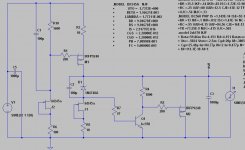
I don't know if people would be interested in a pcb layout I worked out for a version of the shunt regulator. I will attach the image of the slightly modified schematic I have, and if there is any interest I will provide a link to the pcb layout. The reason I modified the schematic a bit is to use parts I had on hand, and also to test the effect of pre-regulating the input with a LM317 the way Walt Jung has done on his super regulator. In simulation it gets rid almost entirely of any output ripple. It is very easy to jumper-out the LM317 and simply not use it. In any case, details can be provided if you guys are interested.
I don't know if people would be interested in a pcb layout I worked out for a version of the shunt regulator. I will attach the image of the slightly modified schematic I have, and if there is any interest I will provide a link to the pcb layout. The reason I modified the schematic a bit is to use parts I had on hand, and also to test the effect of pre-regulating the input with a LM317 the way Walt Jung has done on his super regulator. In simulation it gets rid almost entirely of any output ripple. It is very easy to jumper-out the LM317 and simply not use it. In any case, details can be provided if you guys are interested.
Attachments
Its a nice version, I like the use of a JFET CCS creating a resistor Vdrop voltage reference for the CCS Mosfet. It has to be measured for Idss. I would avoid to wrap a non feedback shunt in a series high feedback IC though. It defies its purpose. By jumper bypass you can test its subjective impression on sonics. But ripple is already vanishingly low so a pre reg is just for curiosity IMO. PCBs are always welcome to be posted.
I forgot to mention that I replaced the three LEDs with a resistor, the reason being that I don't really see the advantage of three LEDs. I'm in agreement with you that the vreg is in there because of my curiosity, and it can be easily bypassed with a piece of wire. I suppose I can just take it out, then I'll post the pcb file.
The LEDS are Vref on their own with very low noise. The 2SK170 I use under them locks their current too, and it is maybe the lowest Jfet for noise. 3 Leds maybe contribute as much noise as a 60-150 Ohm resistor. A 1600 Ohm contributes more and it will drift along with the Idss thermal cycle of the Jfet, which in your version isn't the best there is for self noise. But those are little things to compare. Both versions are good.
ikoflexer said:Let's just say I have a bad tendency to use parts I have at hand, but it's not always a good idea. I will put together a pcb using the LEDs and 2sk170. Do you recommend any particular LEDs?
I recommend experimentation. Use your ideas and parts, listen and compare. I have some certain reasons for choosing some topologies and parts, based on technical and subjective stuff that I evaluate in my own way. Not carved in stone. It only takes time. I just wanted to reply my reasoning behind the LEDS, that is all. LEDS must be 1.7V for the circuit to give the stated current, with the stated R1. If you find them in green they usually come closer to each other statistically. In other color they spread a bit, so you may need sample more. One way is just to string 3 of them together using 1k resistor at their one string end, use a 9V battery, and measure the total drop across them 3. You can subtract 3.4V (Mosfet VGS) from what you measured . What is left will give you the wanted set current for the CCS if you divide it by an adequate resistor. So you can make do with what LEDS you may already have.
Thanks nicoch46!
Here's the pcb image for perusal; one can use either LEDs, or the resistor with this layout. Also, one can use either BF245A or 2SK170 JFETs on the same pcb (they have different pinouts). Interesting that in simulation the bf245a show less noise.
Here's the pcb image for perusal; one can use either LEDs, or the resistor with this layout. Also, one can use either BF245A or 2SK170 JFETs on the same pcb (they have different pinouts). Interesting that in simulation the bf245a show less noise.
Attachments
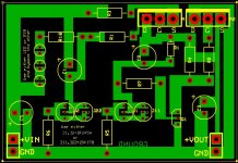
Very practical board! One reason to be flexible with JFETs is their availability. And is good to have different pin out. Stronger JFETS for gain are always less noise. Measure the resistance between D, S. The less, the better for noise. I just measured a 5mA Idss 2N5459, 240R.
A 7.45mA Idss 2SK170, 35R. Measure the BF245A.
A 7.45mA Idss 2SK170, 35R. Measure the BF245A.
Here's a zip file with the pcb layout and supporting files. I used expresspcb which is free to download, so you'll need that program to print the layout. The zip file needs to be extracted in the folder My Documents\ExpressPCB
There's an interesting feature in expresspcb, after you import a netlist file (generated by ltspice in my case) you can click on any pin in the pcb layout and it highlights all the other pins that should be connected to it. Quite useful for correctness checking.
Any suggestions appreciated.
There's an interesting feature in expresspcb, after you import a netlist file (generated by ltspice in my case) you can click on any pin in the pcb layout and it highlights all the other pins that should be connected to it. Quite useful for correctness checking.
Any suggestions appreciated.
Attachments
Cool, I'll measure and let you know. I was busy posting the rest of the files and didn't see your post. There is a .noise analysis in ltspice, I don't know how good it is, but when run with the bf245a it shows pretty much from 1Hz to 50KHz less noise (around 1nV/Hz1/2), whereas the 2sk170 shows double to triple the noise. In practice... probably un-noticeable. I'll probably do the board tomorrow as it's getting late now, plus, I'll wait see if there's any feedback or changes wanted.
I found bf245a in a local store, at about 35 cents canadian and bought them for a different project. I figured it'd be ok to put them in the regulator (cheap), but I'm waiting for 100 2sk170 and will try both.
According to your rule they kinda suck, I measured the resistance between D and S and it was about 220R
Lately though, I've been thinking of using a double-gate fet in the first stage. If only I could find some cheap, to try.
According to your rule they kinda suck, I measured the resistance between D and S and it was about 220R
Lately though, I've been thinking of using a double-gate fet in the first stage. If only I could find some cheap, to try.
Don't worry, if it is to lock a 1.6k resistor for constant Vdrop, it will be swamped and the 1.6k will dominate. With 3mA Idss and 10R3 it will give 140mA CCS. So the Idss sets the current. Do you get 3mA Idss BFs in the batch easily? As for my rule of thumb, think about it... When you short G,S, for making an Idss CCS, what can be dominating the self noise?...Self resistance.
Also the JFET under the Zener must work with VGS(OFF) less than Vbe of the BC BJT. IDSS JFET sources work well when the margin is more than double pinch off. The less the VGS(OFF) the better and always must stay under 0.7V in our case.
Also the JFET under the Zener must work with VGS(OFF) less than Vbe of the BC BJT. IDSS JFET sources work well when the margin is more than double pinch off. The less the VGS(OFF) the better and always must stay under 0.7V in our case.
ikoflexer said:Lately though, I've been thinking of using a double-gate fet in the first stage. If only I could find some cheap, to try.
Make a standard one, and then by all means, experiment. We need evolution. If you manage to find a workable better version with easier JFETS, it will be better for all. Only listen also, after you will be very familiar. What is your audio system comprised off?
ikoflexer said:Would this not, then, imply that a power mosfet with really low Rds(on) be a really good choice to use in the CCS?
As for the matching, I haven't tried it yet, as I was positive that I wouldn't use them in the preamp.
To my reasoning yes. That is why I use chunkier Mosfets than will ever be needed power wise, with low enough RDS ON. The bigger ones are just a little slower (cabling and Cout will slow down any faster, enough anyway) but less prone to oscillations with DIYers too.
salas said:
Make a standard one, and then by all means, experiment. We need evolution. If you manage to find a workable better version with easier JFETS, it will be better for all. Only listen also, after you will be very familiar. What is your audio system comprised off?
Yes, for sure I'll first build the cascoded, buffered version with the 2sk170 that you recommended earlier.
As for equipment, I got nothing special. A few TTs, but only use a Dual at the moment, with a Grado green cart. The other TTs are waiting to be modded. Phono stage, a couple of variations on the opamp elcheapo. I was going to do the Gary Pimm tube phono stage next, but came across you jfet wonder
 and couldn't pass, so the tube one will have to wait. As for power amp, when I need to really hear the truth, I have a 21LU8 based head phone amp with the sony mdr-v6. My speakers and power amp just can't come close to the sound of the head phones, when I need to compare preamps.
I got a truepath kit from 41hz but after I blew a couple of ta3020 chips I gave up. The board from 41hz is IMHO can be GREATLY improved... just look at how many people burn their chips with the 41hz kit. Too bad, I had great expectations from that amp.
Also got a tube buffered chipamp (3886) which doesn't sound too bad.
- Home
- Source & Line
- Analogue Source
- Simplistic NJFET RIAA