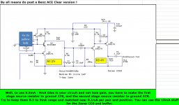
Almost.... In reality, to get 10v on Q2 Drain to GND, I must set it´s Rs to 45 ohm.
I noticed improvements when moving from the previous 9.7v to 10v on Q2D. More explicit highs and more "air".
Lowering second stage gain by increasing it´s Rs seems to lower miller effect (that adds to the 15n cap in the riaa filter).
There is no perceptible increase of noise when doing so.
What should happen to THD when we increase Rs in this jfet ?
PS: I am starting to enjoy the FT-1
I used to have such a 28V ~43dB build, I don't have it anymore to measure THD in FFT and to show you exactly. It donated parts when I moved from the DL160 to the DL103R.") What I remember is it was about 0.03% THD for 300mV with second like 2&1/2 times higher visually than 3rd and no further overtones. Noise floor was something like -110dB @ 20Hz ref 1V out 0dB scale. Don't think that the Miller gets much different for about same second stage gain and say 10R difference in Rs. Having 9-10V on drain is a good balance between B+, Load, gain & Rs in 2nd stage as far as I recall.
What I remember is it was about 0.03% THD for 300mV with second like 2&1/2 times higher visually than 3rd and no further overtones. Noise floor was something like -110dB @ 20Hz ref 1V out 0dB scale. Don't think that the Miller gets much different for about same second stage gain and say 10R difference in Rs. Having 9-10V on drain is a good balance between B+, Load, gain & Rs in 2nd stage as far as I recall.
What I remember is it was about 0.03% THD for 300mV with second like 2&1/2 times higher visually than 3rd and no further overtones. Noise floor was something like -110dB @ 20Hz ref 1V out 0dB scale. Don't think that the Miller gets much different for about same second stage gain and say 10R difference in Rs. Having 9-10V on drain is a good balance between B+, Load, gain & Rs in 2nd stage as far as I recall.Finally found the error.
Left channel 15.3nF FT-1 is faulty... When I first measured it I found that the DMM oscilated between 15.3 and 9.7nF... I did not think about it and was convinced the problem was due to tarnished wires on the cap... I just cleaned it and soldered it in place.
Now I found that it still oscilates during measuring soldered in place.
I will replace it and report back.
Hallo Salas.
I have the Grado Statement Master (0.4 mV, 47K, Mooving Iron) cartridge.
What sircuit is the best for this cartridge.
I read about the Grado Prestige Gold, but it is 4mV (high output).
My Master is low output. Only 0.4mV.
Do I must use 1% resistors and 5% capasitors?
In what watt are the resistors?
Thank you.

All your questions are covered in the pdf guide linked from post#1. Read it.
Salas είσαι κορυφή.
Θα το φτιάξω με την πρώτη ευκαιρία.
thank you
43dB DL160 Salas Riaa update.
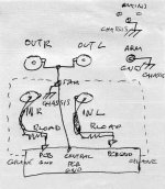
After debugging the difference in gain between channels, I compared this build with the one I made for my Benz ACE M and found it to roll a bit in the lows so I did the following actions:
Remove the RC filter in second stage (gone with the 100r + 680uF)
Now there is no filter in 1st and second stage... (I left a 680uF on the buffer drain just to be sure there is enough juice for transients there)
Add a 1k2r on between the psu Vin and the CCS jfet in first stage. (It was direct)
Remove the trimmer on second stage Rsource and replace it by a 46.5r.
Sound became much faster with outstanding attack and the lows are much cleaner and detailed.
I guess the major benefits come from removing the 680u + 100r RC on second stage, but the fixed resistor in second stage Rs also brings more definition.
Lowering current in the CCS adds some ease to it all.
The Rel Cap polystyrene & Tin Foil in the 15,33nF riaa filter position is much more (alive) than the FT-1, althou it lacks the ultimate extension and sweetness in the highs.
Outstanding results.
Thank you all for the precious help.
Its lowering dissipation on the leds ccs jfet by dropping voltage on that 1k2 you used, not ccs current btw.
Thank you for the correction.... As the jfet acts as a CCS, the current remains the same of course... Sorry for the mistake.
- Home
- Source & Line
- Analogue Source
- Simplistic NJFET RIAA