while my parts (2sk170bl) for the Salas preamp still travel to me, i I quickly and dirty assembled pacific style riaa with 2sj74 bl transistors and RIFA polypropylene caps. Sounds very clean and nice. gain reduced to 0.5V at output -sufficient level to my le monster amp and also lower gain - lower THD.
Next will be Salas preamp and shunt regulator.
And thanks for useful info in this thread.
")
Next will be Salas preamp and shunt regulator.
And thanks for useful info in this thread.
Attachments
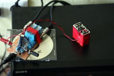
Odd you photograph a phono preamp on a cased CD! I have built 4 Le Pacific based preamps but are yet to build the oroginal. All mine have been based on the boozhoundlabs version of the schematic. I am looking forward to building the original. In the middle of building a 300B power amp so it will be a while.
Hi Salas and all-
I'm gearing up to make a 2nd Salas RIAA, using version V1102F0.pdf. I'll use the 1.2R shunt. P2P on vector board. Initial layout attached.
Cartridge is Benz Glider LO2, 12ohm impedance, 0.42 mV.
For the R's-
Possibly Shinkoh's for the R loads & RIAA R's.
Probably use PRP resistors for the rest.
I scored a bunch of Vishay S102's, Are they any good?
Caps-
47nF's- Siemens polystyrene.
15.1 nF's- Russian light blue 3.765 nF polystyrene caps paralleled to get 15.1 nF.
100nF’s- Russian FT-3’s
470uF's- I have some Nichicon MUSE and Elna Simlic's. Any preference?
I have ~200 2SK170 BL's I'm presently matching. Many are over 8.5mA Idss.
Output capacitor-
I would like to connect this to the Lightspeed attenuator. But the attenuator has ~6-8K input impedance. I will have to use some large output caps? Will it work? 4uF or more?
No parts selection on the shunt yet. Though I read C1 quality is critical.
I'll probably follow SGregory's PSU and filter (R1 C1 L1 C2 L2 C3) from post 5529.
Any advice would be greatly appreciated.
Cheers- Kent
Attachments
Hi! That is what the simulator gives for that CCT when driving 7K load with a 5.6uF C7 (attached). I think its adequate and still skips some low disc warp gently. Yes, 1.2R's Vref cap is shaping the tone enough. The output film too, but plays second fiddle.
Muse or Silmic, hmm depends on the overall character its going to strike in combination with the TT. You should check for real.
About Vishay S102 I have only seen opinions on the web. They say TX2575 ($) is the one and S102 comes next. Vishay is top quality spec any way and I would do a test in the load and Riaa positions if I had some, so to evaluate if I could hear something in the long term.
Since your cart is Benz Glider 0.42mV better do the slight changes on previous page's post #5875 that gave 58.4dB to smpkje since he felt he needed a bit more with his same output spec Shelter 501.
Best regards and good luck, the layout looks logical.
Attachments
Thanks, Salas! 5.6uF it is. Have some old 4uF WE PIO's that will help me here.
Vishay 102S's- I have quantity of 40k, 70k, 300k, 5k and 50R. Also Jordan, Cohu, HP precision. Some R experimenting is in order.
What if I used some of my higher testing (>9mA Idss) sk170's instead of tweaking R values to get higher gain?
Vishay 102S's- I have quantity of 40k, 70k, 300k, 5k and 50R. Also Jordan, Cohu, HP precision. Some R experimenting is in order.
What if I used some of my higher testing (>9mA Idss) sk170's instead of tweaking R values to get higher gain?
If you got many more parts higher than 9mA, you can use 40V B+ and concentrate around 9.3mA Idss (especially for the first stage try to be spot on that), and just use R2 1R5. That will give you near 58dB maybe a hair less or more. You can't keep all the same, drop more Idss in and just get gain, bcs it will bias wrongly. But the above is minor change and you can utilise your fets stash better.
....I do like the hash filter that Eli Dutman has been pushing......
Hi SGregory-
What is Eli's hash filter? I couldn't find a thread about it here.
You also mentioned 'removing a carbon comp resistor' in -post 5526. What resistor is that?
I've enjoyed reading your Salas RIAA development. Can't wait to get mine done. Matching a pile of jfet's presently.
Best- Kent
Jfets matched idss
Ok...whew.
So after grouping ~150 k170 jfets into quick current piles, i had 67 that were 8mA or better.
Got out my nice PSU, set up my meters and accurately measured the >8mA pile. 9.00vdc. Room at constant 70'F. Gave each jfet ~10 min to settle. Used proto board- no hands touching jfests.
Using 0.02mA difference as max, I came up with 16 pairs-
8.12____8.69____9.27____10.20
8.13____8.70____9.27____10.21
8.16____8.73____9.83____10.29
8.17____8.73____9.84____10.30
8.65____8.94____10.10____10.64
8.66____8.95____10.12____10.66
8.66____8.98____10.19____10.68
8.68____8.98____10.20____10.70
Should I test for Vp as well? I know matching is a hotly debated subject and I'm wondering if Idss is enough.
The attached graph shows test result dispersion.
Cheers- Kent
Attachments
Last edited:
-Vp and Idss will affect bias when Yfs (gm) will affect gain. More Idss indicates more -Vp and top Yfs, but Idss is not affecting transconductance changes severely when the bias Id is the same (1st pic). So to keep same Id in a circuit without trimming resistor values for each fet, we need similar Idss and -Vp. As you can make out, to really say we got two identical JFETS we need to trace em out dot to dot measuring or have a tracer machine. If you can measure -Vp (VGS(OFF)) for a few samples around the 6-7-8-9-10 Idss marks we could see if the second attachment from TOSHIBA is still relevant. In general your batch is well proportioned and you have many around the 8-8.5 Idss reading in the end. Good thing is that in circuit Id and gain followed the modelling very well in the recently posted made and measured circuits that followed the PDF resumed values and instructions.
Attachments
Okay. Will test -Vp soon of the selected fets. I need to get out my other supply as the one I'm using only goes to 14V.
BTW, I'm testing leds. I noticed different voltage drops, depending on the Idss of the jfet. Example-
red led with 7.97 Idss jfet = voltage drop 1.595V.
red led with 10.49 Idss jfet = voltage drop 1.610V.
Yes, very little difference. But what Idss should I shoot for on the jfet with this test?
Thanks for all the help, mate!
-Kent
As I write in the PDF, better use the FETS you will use for Q5s as Idss current sources to measure the relevant LEDS to put in each channel. That will bring it even nearer. Use two FETS around 8-8.5 also, so the drops on the protection resistors will be in spec. Its normal LEDS will change Vf a little with different enough current as they emit stronger or softer.
Yes. One Jfet and an LED for testing. Those you designated are so near they will not change the LEDS Vf at all. I spec all Jfets around that mark so the calculated resistors will drop predictably. Same and conservative dissipation for Q5s. You should normally get 8-10V across Q5 in circuit if all is in the ballpark.
I did a check. On is a really muted ''plop''. Off is a ''bang'' though at the level of normal signal given the volume pot's position. Not louder. Use a back panel switch so they would be inclined to reach for switching off the amplification first, or use an output relay circuit.
- Home
- Source & Line
- Analogue Source
- Simplistic NJFET RIAA