Iko you started your Vietnam tests again! Its an unstopable urge, isn't it? Almost a hunger.
 I'm developing
 An externally hosted image should be here but it was not working when we last tested it.
reg, and it better

Though I'm afraid ....
An externally hosted image should be here but it was not working when we last tested it.
European audiences over 5yrs old can handle this.

Last edited:
Put the R of the CRC back in.I had a CLC filter after the rectifier, that fed the shunt. C1 was 100uF, R was 22R, and C2 was 10000uF. .................. Changed the shunt and set it to 20V out, and the ripple at the output was insignificant, below 100uV. I should try the shunt with a smaller cap too.
It attenuates the hum, slightly. A far higher attenuation of the Higher Frequency buzzes and RF is achieved by keeping it in.
It is a low pass filter. 1r0 and 10mF has F-3dB @~16Hz
It will attenuate 60Hz by ~9dB, but it will attenuate 600Hz by ~29dB.
The 1r0 will lose just 3V when passing 3A. I would be tempted to arrange that the R drop between 5% and 10% of available voltage when passing maximum current. Then select the C to achieve significant mains frequency attenuation.
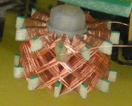
If rotating the TX and using the lid does not cure the buzz, maybe it is a noisy zener
That would be hiss, not buzz though.
Hi Salas et al,
I've rotated the transformer to different orientations and installed the lid but no change. On my test bench, when I clip lead the signal ground to the case/power ground, the noise on the outputs drops to 100-200 microvolts with the inputs shorted. This makes me think it is a ground loop problem when installed in my system. More tests coming.
Thanks again,
John
How much more is it without clipping the sgnd to chassis? Is it hum or buzz?
Fortunate, because if it was mainly audible field noise, you woulld have very little way of keeping it like it is constructed now. Would lead to major hassle. Keep on looking so to get it under audible threshold with your given total system gain & speakers sens. Good luck, and let us know.
Fortunate, because if it was mainly audible field noise, you woulld have very little way of keeping it like it is constructed now. Would lead to major hassle. Keep on looking so to get it under audible threshold with your given total system gain & speakers sens. Good luck, and let us know.
Without the clip lead to ground, it's 8-9 mV in one channel, about 30mV in the other. It seemed more like a buzz in the system last night, but when I put a clip lead from the turntable chassis to the ground lug on the preamp it went way up in volume and changed to a hum.
Without the clip lead to ground, it's 8-9 mV in one channel, about 30mV in the other. It seemed more like a buzz in the system last night, but when I put a clip lead from the turntable chassis to the ground lug on the preamp it went way up in volume and changed to a hum.
Big difference. So we now know that by fixing the signal ground to chassis it gets down from 10's of mV to 100-200uV. We also know that you must not mess with the TT. Next thing I would do, is to keep measuring while clipping to alternative take off points. Like the input RCA's ring or the output one, the point where shunt gnd meets audio circuit's gnd etc. If you manage to get it under audible in your system, its passable. Before you finish, try a 10R between chassis and your best point, just to see if it helps further or not. In general, if having instruments, especially FFT, where you can see both THD and offensive noise bands, as well as noise floor, you can tune enough such a circuit by finding best operating points for given JFETs by using trimmers over source resistors, manipulating the ground, matching the channel outputs exactly, altering the layout etc. And you would be educated by watching the impact of things that you don't directly hear if low enough, but how they up analysis and focus when optimized. Like that every two box construction has a smooth noise floor when single box has grass from the trafo and little peaks with octave spacing and many other things related to the shunt parts, its Vref quality and other. But as you made it looks good enough if you can empirically knock the buzzing really down.
I like big but that is way out too big... enormous
No girl has ever told me !

- Home
- Source & Line
- Analogue Source
- Simplistic NJFET RIAA


 Life's good with nice DIY, not LG.