To make myself completely clear, I read you say that too much series resistance is bad, so if 355 volts is too much for the circuit I'm thinking of increasing the regulator current to drop as much voltage as possible in my CRC filter, maybe a 800 ohm resistor would be OK.
*Now I'm thinking that at startup before the regulator starts sinking current maybe there would be too many volts for the transistor regardless of my resistor. Damn I hate to be in the dark. I shouldn't have started this nightmare.
*Now I'm thinking that at startup before the regulator starts sinking current maybe there would be too many volts for the transistor regardless of my resistor. Damn I hate to be in the dark. I shouldn't have started this nightmare.
Last edited:
OK thanks, that resistor sets the current but I'm worried about the MPSA92. In your 400 volts schematic you replaced it with the 2n6520. My question was: can the MPSA92 take 350 volts input voltage? I also have mj350's but, as I know next to nothing about transistors, I'm afraid a copy and paste wouldn't work. My ideal B+ out is 300 volts.
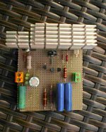
I must add that I was measuring things when, for a fraction of a second, the lights went out (LEDs) but everything went back to normal. After a while I smelled the stink and sure enough, that resistor was toast. The regulator still works.
*OK, I read 840 Ohms between Gate and Source. Is this normal?
*OK, I read 840 Ohms between Gate and Source. Is this normal?
Last edited:
Some oscillation must have happened while you were probing. The resistor probably survived though charred. Else, without gate drive it would not work.
Replace the gate resistor and use a low ESR LEDs cap when able. That one cap you got now just remove it.
It should read 3-4V between gate and source when the 9240 is working. Congratulations for having a hardwired reg working on first time despite a small incident.
Don't probe around the MOSFETs if not necessary. It should be hot on both MOSFETs when everything works of course.
Measure the voltage drop on R1 and divide by its value to know at what CCS current your reg runs.
If you did not use a load on the output then the parallel part (840) was at its hottest because it did not share a portion of the available current.
You should keep a proportion of 20-30mA extra current on top of your target load max demand. That you can arrange by judging R1 value.
*For anybody else reading this is the SSHV0 we talk now with BJTs in the Vref, big Mosfet etc. As in post #2. A retro design that many still like for its "warm" tone.
OK thanks, that I will do. I have to congratulate you as well because it took me ten seconds to realize my preamp sounded so much better with your regulator on.
The circuit regulates - playing with the trimmer the minimum difference between voltage in and voltage out is 36 volts. This is my second circuit in this kind of board, first one was just a single transistor (a Dallas Rangemaster) guess I was lucky until I pushed my luck too far, that is.
The circuit regulates - playing with the trimmer the minimum difference between voltage in and voltage out is 36 volts. This is my second circuit in this kind of board, first one was just a single transistor (a Dallas Rangemaster) guess I was lucky until I pushed my luck too far, that is.
Salas:
I'm using your SSHV2 feeding four triode halves (balanced amp) and each one of the triodes is CCS'ed on the anode with cascoded DN2540's. Normally when running this circuit i have a small 0,1 - 1,0uf coupling cap before the ccs's. And today i do have two small 0,1uF caps there, and it sounds really great to my ears. But would you recommend to remove them? or should i have one of them left or what would you think?
I'm using your SSHV2 feeding four triode halves (balanced amp) and each one of the triodes is CCS'ed on the anode with cascoded DN2540's. Normally when running this circuit i have a small 0,1 - 1,0uf coupling cap before the ccs's. And today i do have two small 0,1uF caps there, and it sounds really great to my ears. But would you recommend to remove them? or should i have one of them left or what would you think?
Salas:
I'm using your SSHV2 feeding four triode halves (balanced amp) and each one of the triodes is CCS'ed on the anode with cascoded DN2540's. Normally when running this circuit i have a small 0,1 - 1,0uf coupling cap before the ccs's. And today i do have two small 0,1uF caps there, and it sounds really great to my ears. But would you recommend to remove them? or should i have one of them left or what would you think?
When its stable as a system better not mod it further.
When its stable as a system better not mod it further.
But i remember somewhere that you did recommend to not have any coupling caps after the SSHV2? or am i mistaken? i cannot find where but i remember "slow sounding" or something like that.. or maybe that was with the SSLV1.1?
But i remember somewhere that you did recommend to not have any coupling caps after the SSHV2? or am i mistaken? i cannot find where but i remember "slow sounding" or something like that.. or maybe that was with the SSLV1.1?
Surely you mean "decoupling caps"? Coupling caps are for coupling the AC signal...
Alex
")
Generally speaking the shunt-regulator should not have any additional capacitors at its output. It is the question of stability and efficiency. But we all know that the main goal - purely practical. If you prefer the sound with the capacitors who has the right to say that this is wrong?...i remember somewhere that you did recommend to not have any coupling caps after the SSHV2?...
I'd compare the sound with and without the capacitors, but in reality - when something works, there is no need to improve anything.
Last edited:
The anode CCSs in the audio circuit can be benefiting from the local decoupling. When they add up to a value that in conjunction with the stray inductance in between don't destabilize the phase margin of the regulator all is well. In another occasion they could (small C total, not much inductance-resistance in between). So its a practical matter.
Salas.....I am using one SSHV2 board to power a pair of resistor loaded, cap output VT-25A line amp.....could you suggest (give an example of) a pair of anode CCSs to replace the resistors please.....
Attachments
- Home
- Amplifiers
- Power Supplies
- Simplistic MosFET HV Shunt Regs