A few days ago I changed Q2 to MJE5731A . Sounds better. I'd like to understand why but looking at the data sheets I don't get it. Anyway, I think it's worth a try if you have them on hand.
It shows flatter extended hFE curves but beyond our bias range here. Did you measure its hFE? Can have more, or can have more Vbe for the Jfet. Please measure Vbe at its circuit bias and tell us. Looks like having more Cob' normally since its more powerful although you never know where Cob' is judging by stated Ft. That could change the phase enough. Sure thing is it is TO-220 and I prefer that in a hot environment, plus has more voltage. So its nice it fits. In what way you found subjective changes, and is there a photo to see where it lies on the board? Also what is the output voltage you work with, again?
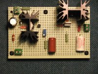
Well that's good timing. I just pulled the boards out so good time for a photo. Just switched in another board - same circuit but with a cascode DN2540N5 / IXTP01N100D for the CCS.
Subjective? Hmmm, there's a sort of grey bright hardness in the sound that I hear with the MJE350. This to my ears is improved with the 5731A. I guess a little less harsh or a bit sweeter? The tone somehow just feels a little more realistic and I relax when I hear it after listening to the 350.
Output V is about 360VDC.
I'm hearing a few things with the DMOS that I don't like but that could just be implementation. I'll play with it and listen for a few days and then put these ones back in. Will measure circuit voltages and post them as soon as I do.
Thanks Salas .
Attachments
Hmm it is very near the main sink indeed. TO-220 has a benefit there for perceived heat. You had been using the MJE350 beyond max Vceo? Can have both better linearity, hFE, and more Vbe the new one. Datasheet does not show in such low current. Measure Vbe when back in service, its interesting. The DMOS (single) I have written sometimes back in this thread that I have not opted for too... Cascode, lets see for your final evaluation.
")
Hi Salas,
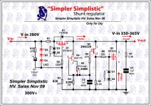
I just powered up my SSHV but was having problem achieving the 300vdc target I was expecting from the 315Vdc Vin as measured at the 47R input resistor. What I got was only 90Vdc even adjusting the VR to the max. The 3 LEDs did not lit up. Output load is 10kohms. What have I did wrong? Thanks in advance for any advise you can give.
I use 20H 55ma choke (DCR 390R) in place of the 470R/5W resistor.
R1 = 47R
R3 = 68 K/5W
R4 = 180 K/2W
R5 = 5.6k
R6 = 220R
Trimmer = 500R
Hi Salas,
I just powered up my SSHV but was having problem achieving the 300vdc target I was expecting from the 315Vdc Vin as measured at the 47R input resistor. What I got was only 90Vdc even adjusting the VR to the max. The 3 LEDs did not lit up. Output load is 10kohms. What have I did wrong? Thanks in advance for any advise you can give.
I use 20H 55ma choke (DCR 390R) in place of the 470R/5W resistor.
R1 = 47R
R3 = 68 K/5W
R4 = 180 K/2W
R5 = 5.6k
R6 = 220R
Trimmer = 500R
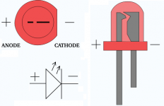
LED does not light, then the CCS is your problem!
Check to see if connection led the wrong vacuum?
ie the opposite direction!
Attachments
Last edited:
Does anyone know if there is a schematic here that would work with a Dynaco MarkIII clone?
Only for the driver part not for the power output. Tell us what are your voltages at points RED and 5 on this schematic so we can suggest a reg.
Attachments
Salas,
Thanks for responding so soon. I assume when you say "red" you are talking about the AC output from the power transformer? And then lug 5 downstream of the 6800 ohm resistor?
If that is the case I will have to get back to you. I don't have the amps. I'm just collecting transformers and other parts now. If they are both good, I'll be using a pair of power transformers from an old 4x6v6 amp. And the output transformers are a pair of Hammond 1650n's. I plan to use a SS bridge rectifier with a choke input.
The schematic calls for 480 volts DC from the power supply. How much voltage would be needed beyond that. From my little experience with regulators you need more input voltage than your output target.
When I finish the first power supply I'll contact you with those voltages.
thanks, Kevin
(right now I'm going to listen to Segovia on my Mark VI's)
Salas,
Thanks for responding so soon. I assume when you say "red" you are talking about the AC output from the power transformer? And then lug 5 downstream of the 6800 ohm resistor?
If that is the case I will have to get back to you. I don't have the amps. I'm just collecting transformers and other parts now. If they are both good, I'll be using a pair of power transformers from an old 4x6v6 amp. And the output transformers are a pair of Hammond 1650n's. I plan to use a SS bridge rectifier with a choke input.
The schematic calls for 480 volts DC from the power supply. How much voltage would be needed beyond that. From my little experience with regulators you need more input voltage than your output target.
When I finish the first power supply I'll contact you with those voltages.
thanks, Kevin
(right now I'm going to listen to Segovia on my Mark VI's)
RED (DC) I see on that schematic as midpoint of output transformer's primary. That will show your real B+ in a build, and eyelet 5 will show the real HT voltage for driver circuitry. Their difference divided by 6800R will give the front end's current draw. Then we can set target parameters for the operating point of a suitable reg. SSHV can operate even over just 10V In-Out difference.
Wich type are proper heatsinks for IRF9610, MJE350 & IRF840?
Think big for a 175V 40mA output I am using a 8"x3"x2" sink. The calculations are listed on the PCB sellers thread.
BE WARNED
I would like to remind people that not only you're dealing with high voltages, but you may decide to pass some higher current as well, and the heat that needs to be dissipated can be huge. When you make changes, i.e. adjustments to this type of circuit, thinking that you raise the output voltage by a little bit, or the idle current, you have to consider the value of capacitors in the circuit, and all the other parts. Will they take the higher voltage/current? Don't make changes lightly, or it will blow in your face. The starting voltages that some of the parts go through are completely different then the voltages that they live at once the circuit gets to its operating point. Can the parts that those voltages/currents? Unless you're very experienced, best to stick with a circuit that has been already built, and there are several examples in this thread. If you're comfortable to risk, you obviously do that on your own, but ALWAYS keep in mind the possibility that parts could explode and catch on fire. So be prepared, wear eye protection, and take all other precautions to not start a fire or get zapped.
I would like to remind people that not only you're dealing with high voltages, but you may decide to pass some higher current as well, and the heat that needs to be dissipated can be huge. When you make changes, i.e. adjustments to this type of circuit, thinking that you raise the output voltage by a little bit, or the idle current, you have to consider the value of capacitors in the circuit, and all the other parts. Will they take the higher voltage/current? Don't make changes lightly, or it will blow in your face. The starting voltages that some of the parts go through are completely different then the voltages that they live at once the circuit gets to its operating point. Can the parts that those voltages/currents? Unless you're very experienced, best to stick with a circuit that has been already built, and there are several examples in this thread. If you're comfortable to risk, you obviously do that on your own, but ALWAYS keep in mind the possibility that parts could explode and catch on fire. So be prepared, wear eye protection, and take all other precautions to not start a fire or get zapped.
Depends on dissipation in each settings use. There is no single answer.
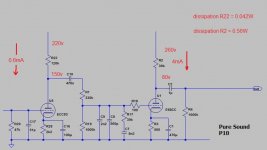
I do a couple of regs one for Pure Sound MM phono & Audionote SRPP 6922 preamp. I have a couple Quanghao SSHV
An externally hosted image should be here but it was not working when we last tested it.
Attachments
Last edited:
- Home
- Amplifiers
- Power Supplies
- Simplistic MosFET HV Shunt Regs