Q2 are cold on both boards.
But on new board I got slight dif results=
Vout = 40 V @ 88mA
Q1 Vds = 95 V
Q1 Vgs = 2,3 V
Q2 Vds = 1,7 V
Q2 Vgs = 1 V
__________________________
Felipe, going much higher at Vin only rewards by 1 or 2 mA. more.
__________________________
euro21, I understand now you duplicated the cascode, please forgive me my bad at reading in first glance.
It seems the results very close to the specification.
But is no other way than paralelling? I dislike the idea....maybe another design... one upper, I like the speed of Ixys in the upper, and two DN2540 to take the heat??
Jordi could you use for Q1 & for Q2 IXTP02N50D (beefy 200mA)?
Jordi could you try this please?
I remember the other day when pcb has those small row pins, getting worse results using IXTP02N50D.Jordi could you use for Q1 & for Q2 IXTP02N50D (beefy 200mA)?
Mainly placed as Q1. But bareable when Q2.
I thing is needed two Q1 or one more powerfull than DN2540.
Is that posible?
Is cold, and agree Vgs Q2 reading 0,1V like a dead one, I will change later,Q2 is dead? Does it warm up at all?
Q2 is IXTP02N50D, I have spares.
thanks
And Felipe, the other in Q1 is DN2540
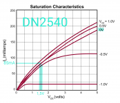
I find it in the specification pdf, Is a shame that IXYS not provide also saturation Id current curvesIf you use DN2540 as "lower" FET, in the datasheet the saturation Id current at -about- 1.5V Vds, 0V Vgs is about 85mA.
That's why I suggested to use duplicated -parallel- CCS (the other reason is the Q2 limited current capacity).
Attachments

") Thank you Bela.
Thank you Bela.
Thanks Bela, I appreciate the schems, great this one including Ixys.
I will see what can I do for an easy comparison when listening each schematic performance.. maybe a perforated board with row pins soldered and contact paste to help filling the holes.
In the meantime waiting for the parts, I succed in reply the conditions where 77V/170mA. are archieved this past days.
At the time, I have had a solder bridge Drain to Source in Q1.
So bypassing Q1, confirmed the reg is in again in working order, and good sounding without the cascode!
Could I ask why can't be used only two BSP149 in cascode?It was a sample to show, that BSP149 suitable for 170mA CCS as "lower" FET.
If you want to test it "in vivo", use IXTP02 as "upper" FET.
This simulation use paralleled 01N100 to achieve 200mA capability.
And yes, some heatsink need.
View attachment 1132185
Better single Mosfet than that. I had tried it and there's hiss.Salas what about to use a LM317 as CCS to substitute one N depletion mosfet?
I know not the same perfomance but for the application uses Jordi could be enough and a simple solution.
They are sense & force four wire remote sensing outputs. Kelvin.@Salas
Looking at the SSHV2.
What I don't understand is the S+ and F+
Looks like it is 2 outputs ......
Yes, it cancels the force wires resistance by sensing voltage for the error amp at the load's node. Sense carries no current.
Because it extends the loop area beyond the board, has to be applied with care not to become a noise antenna. So not too long & thin twisted. Or even better, coaxial sense wiring.
Because it extends the loop area beyond the board, has to be applied with care not to become a noise antenna. So not too long & thin twisted. Or even better, coaxial sense wiring.
- Home
- Amplifiers
- Power Supplies
- Simplistic MosFET HV Shunt Regs