That C3 probably has very low HF impedance and upsets the specific reg. No bad result expected in tossing it though, Zo there is already very low as poty said.
Keep the R2-C2 R3-C1 cells. Those are useful progressive noise filtering and buffering RC cells between stages. If their resistors would have been left there alone then the signal following AC current drawn by the valves would have created an analogous voltage across those R. In other words signal modulation of the rail voltage. Nobody wants that. The C elements are there to hold local energy at low impedance very near to the points of consumption. The resistors create time delay of charge and make the noise filtering go deeper in frequency. They work together with the capacitors for that and as a dropper tool alone for bringing each stage's rail DC to what level the designer planned.
thanks Salas for explanation. I just worry because R2 is small and C2 might have same impact as C3 does to Reg.
Each capacitor max. voltage at least 630V;
68k resistors will dissipates over 0.5W, so use 5W ones;
IRF840 needs large heatsink (about 3-4 K/W);
Don't use larger raw supply voltage than 400-420V, except CCS heatsink would be too small.
p.s. 2SA1381 will dissipate over 400mW, so use larger heatsinks (than small plate ones).
I have put in an IXTP01N100D and larger heatsinks for the 2SA1381’s with better results, though they still produce a lot of heat at 40mA. The rest stays pretty cool, no excessive heat until so far. Still have to swap the 10uF for a 630V version. Probably better.
So I was searching the internet to learn more about shunt regulators and found this explanation from K&K audio. They sell a regulator based upon the SSHV2:
“For push-pull and/or differential circuits the applications story is different. Since the signal current in the two triodes flows in opposite directions there are no big current swings that result in power supply voltage fluctuations. In fact, one oft-repeated advantage of push-pull circuits is that power supply design is simpler for this reason. However, there is still some variation due to audio signal, because in push-pull circuits that are not properly differential in action the consequences of imperfect tube matching show up in power supply voltage modulation. A shunt regulator can be applied to reduce this effect by a large factor. In fact, I became interested in shunt regulators when I found that the application of a shunt regulator to the center tap of a line output transformer in a transformer loaded differential stage improved the sound to a pretty significant degree. Even in practical tube differential amplifiers with very well-matched triodes and very good quality common cathode current sinking the positive sonic effect is readily heard. In this case, I found that relatively little shunt regulator current (just enough to keep the shunt regulator operating nicely plus a small engineering margin) sounded the best with a well-matched pair of triodes in the stage. Increasing the current shunted through the regulator beyond just enough to sustain regulation actually decreased sound quality.”
He gives an example:
“This time we will examine a push pull circuit. Again, starting with the current source heat sink, the voltage to be dropped across the current source is 300VDC-250VDC=50VDC and the current through the current source is 26mA (20mA for the circuit and 6mA for the shunt regulator, as discussed earlier). So the heat dissipated in the heat sink will be 50 x 0.026 = 0.8 watts. So from the heat sink info, it’s clear that a 1” heat sink will again be more than adequate.
For the shunt regulator the steady state current is only 6mA (minimum shunt regulator operating current plus a little margin for mischief) and the voltage dropped is the regulated voltage, 250VDC. So the heat dissipated by the heat sink will be 250 x 0.006 = 1.5 watts. So once more a 1 inch heat sink will be adequate.”
What do you think of this? Could these settings be applied for my setup, the Alan Wright PP-2C? (Look at my schematics posted earlier)
If so, it would be most convenient, for it results in much lower heat dissipation in the 2SA1381’s and it is supposed to increase the sound quality.
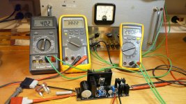
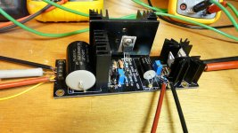
I took these settings for a test run and the regulator seems quite stable, see photos.
Meters from left to right:
Voltage IN (V)
Voltage Out (V)
Voltage TP (mV)
The load resistor(s) value is approx. 19k.
How about another Spice simulation, euro 21?
Tia,
Rovano
Attachments
Last edited:
From what I remember by just looking at the K&K website photo (I wasn't involved consulting into that product) it seemed to me more like combining SSHV1 output style with SSHV2 CCS style.
The less spare current allowed for consumption in its output MOSFET the higher the output impedance of the reg is the direct technical consequence.
The less spare current allowed for consumption in its output MOSFET the higher the output impedance of the reg is the direct technical consequence.
Rovano.
The simple example dissipations need a more thorough analysis.
He shows 300V - 50V leaving 50Volts dropped across the CCS.
You should be looking at the variation in the 300Vdc supply that can occur as mains voltage changes.
I suggest you allow for +-6% (or actually measure your maximum DC voltage with a Variac as your temporary supply).
That 6% tolerance amounts to +-18V on the 300V.
Max becomes 318Vdc
Take off your 250V to leave a Vdrop of 68V and apply you 26mA of continuous current. Dissipation for highest mains voltage becomes 68V*0.026A = 1.8W
Now consider the consequences of a temporary fault at the load. Could the CCS be asked to drop much more than a nominal 50V? what is the load presented only sufficient reactance to leave 80V across the load? The Vdrop on the CCS becomes 300-80 = 220Vdrop.
Dissipation during this fault incident would be 220V*0.026A = 5.7W. Will the CCS survive?
Similarly the shunt regulator may have to dissipate the whole CCS output, if the load became temporarily disconnected.
200V and 26mA gives a dissipation of 5.2W
Will the Shunt survive?
Hi Andrew,
My Voltage drop will be lower than K&K’s example. I am aiming for 400 – 380V. If you take a margin of -+6% that would be 424V max. and 376V min. Dissipation max. > (424-380)*0,026 = 1,14W
In case I would set the regulator for a normal value of 40mA, dissipation max. would be (424-380)*0,04 = 1,76W right?
If the load would be disconnected, will the regulator try to ‘eat up’ all the power? If so, the max. dissipation would be 424*0,04 = 16,94W. Can we then not conclude that when the load is disconnected there will always be damage? The damage in this case is even worse than when the regulator is set for 26mA > 424*0,026 = 10,4W or do I make a mistake here?
Regards,
Rovano
Do you think the regulator will work at 376V in? According to Salas' datasheet the input-output difference should be more than 10V. So you will have to aim to (380+10)/0.94=415V in "normal" state....I am aiming for 400 – 380V. If you take a margin of -+6% that would be 424V max. and 376V min.
Your proposed voltages don't work.Hi Andrew,
My Voltage drop will be lower than K&K’s example. I am aiming for 400 – 380V. If you take a margin of -+6% that would be 424V max. and 376V min. Dissipation max. > (424-380)*0,026 = 1,14W
In case I would set the regulator for a normal value of 40mA, dissipation max. would be (424-380)*0,04 = 1,76W right?
If the load would be disconnected, will the regulator try to ‘eat up’ all the power? If so, the max. dissipation would be 424*0,04 = 16,94W. Can we then not conclude that when the load is disconnected there will always be damage? The damage in this case is even worse than when the regulator is set for 26mA > 424*0,026 = 10,4W or do I make a mistake here?
Regards,
Rovano
If you are predicting a maximum of 424Vdc and a minimum of 376Vdc then you CANNOT get 380Vdc to drive your amplifier.
The CCS and Shunt regulator requires a MINIMUM voltage differential from Vinput to Voutput to operate properly.
Do you know what Vdrop your CCS+Shunt regulator requires to operate properly?
Designing a High Voltage Regulator is an onerous responsibility.
+-6% on a 10Vdc supply is not a big concern, (but big enough that it warrants a thorough analysis).
+-6% on a 400Vdc supply is rather different.
Designing for a start up Vdrop of 22V is very different from designing for a 422Vdrop at start up!!!!!
I have built designed, built and sold (at parts cost only - no labour costs) a few custom Salas Style regulators to a couple of Members.
I would not volunteer to build any HV shunt regulators for Members.
Last edited:
Hi Andrew,
I obviously made a mistake. Let me ask you this: I require 380V and a load current of 20 mA. What, in your opinion, should be the right settings?
Regards,
Rovano
do you know your range of mains voltage?Do you know what Vdrop your CCS+Shunt regulator requires to operate properly?
Hi Andrew,
I have not been building yet, but my raw DC should be around 450V DC. I have to bring it down by applying an extra power resistor to the required voltage of the regulator. (see my schematics posted earlier). Anything between 450 and 400V is possible. Mains in my country is 230V AC +- 10% according to the standards of the power company.
As I understood, there should be a difference between in and out of at least 20V?
Regards,
Rovano
Dear Salas.
You do not recommend putting a capacitance on the output of the stabilizer more than 15 μF.
Is this due to the sound quality or the electrical features of the stabilizer?
I want to try the concept, according which the output capasitors of the stabilizer is extremely large.
For example, at a voltage of 294 V, I plan to have 6800 μF at the output of the stabilizer (and slightly more in front of it).
May such a capacitor lead to failure of the stabilizer or amplifier?
380Vdc as your required output gives the minimum input to the shunt regulator as 380+20 >= 400Vdc (including any ripple).Hi Andrew,
I have not been building yet, but my raw DC should be around 450V DC. I have to bring it down by applying an extra power resistor to the required voltage of the regulator. (see my schematics posted earlier). Anything between 450 and 400V is possible. Mains in my country is 230V AC +- 10% according to the standards of the power company.
As I understood, there should be a difference between in and out of at least 20V?
Regards,
Rovano
When your mains is at 230-10% = 207Vac (that is very low, the harmonised voltage in the EU is 216Vac to 253Vac).
You need a transformer that gets your 400Vdc after the rectifier/s when the mains voltage is at 207Vac. A solid state rectifier will drop about 0.7Vf thus your transformer will need to be 230:315Vac
315*sqrt(2)*207/230 = 400.9Vpk and subtract the rectifier and you have achieved your 400V required as your input to the regulator.
Now look at max mains voltage: output DC will be 315*1.1*sqrt(2)-0.7 = ~ 489.3v
The Shunt regulator now has to drop 489.3-380V = ~109Vdrop.
At 26mAdc this amounts to 2.8Watts
You will need to account for transformer regulation which I have ignored in the example above. You can probably do that by adjusting the dropping resistor you mentioned earlier.
Last edited:
Hi Andrew,
The 10% +- margins are extremes, but still within the conditions of the mains connection of the power company. Practically they never occur. In my case mains is always around 230V. On sunny days it might even go up to 234V as I have my own PV installation. I have never measured anything below 225V. In the Netherlands we probably have the best power grid of Europe.
As you mentioned, I will be able to adjust the incoming voltage to 400V by applying the right dropping resistor.
Now, back to my initial question: Will a quiescent current of about 6mA for the regulator alone suffice to make it work properly? Will this setting, as K&K claims, increase the sound quality in a differential amp stage? I have been testing this setting and it seems to work just fine but Salas says that the output impedance of the regulator will go up as a consequence of a lower than 20mA quiescent current. The advantage of a lower current is less dissipation, obviously.
Maybe I just have to try different settings when the amp is completed…..
What I still can do now is measure the temperature of the heatsinks of the two KSA1381’s with a setting of 40mA. What is your opinion?
Regards,
Rovano
In my case mains is always around 230V. On sunny days it might even go up to 234V as I have my own PV installation. I have never measured anything below 225V. In the Netherlands we probably have the best power grid of Europe.
227-237V in my case but 90% of the time it stays above 230V usually at 233V (Athens, Greece)
Dear Salas.
You do not recommend putting a capacitance on the output of the stabilizer more than 15 μF.
Is this due to the sound quality or the electrical features of the stabilizer?
I want to try the concept, according which the output capasitors of the stabilizer is extremely large.
For example, at a voltage of 294 V, I plan to have 6800 μF at the output of the stabilizer (and slightly more in front of it).
May such a capacitor lead to failure of the stabilizer or amplifier?
Due to electrical features. Much capacitance at its output diminishes for gain and distorts for shape its OLG (open loop gain) characteristics.
Dynamically (during charge) it may even lead to failure of parts in the regulator.
227-237V in my case but 90% of the time it stays above 230V usually at 233V (Athens, Greece)
I have to come back on my earlier statement: In Greece they also have an excellent power grid
")
It has a very difficult geography for fully developing and maintaining a reliable grid. Due to the thousands of islands and many mountains. The regional consumption varies enormously between wintertime and summertime also. Due to air conditioning in the city and the seasonal boom of tourists in the islands. Its not a bad grid given the circumstances. Wind and solar power local resources are plenty to keep on adding though.
It has a very difficult geography for fully developing and maintaining a reliable grid. Due to the thousands of islands and many mountains. The regional consumption varies enormously between wintertime and summertime also. Due to air conditioning in the city and the seasonal boom of tourists in the islands. Its not a bad grid given the circumstances. Wind and solar power local resources are plenty to keep on adding though.
Yes well, in the Netherlands it is all flat and no rocks and stones. All cables are in the ground except some of the very high tension lines. Not so much fluctuation in consumption, easier to maintain.
And, extremely important: The grid has not been privatised (yet)!
Last edited:
- Home
- Amplifiers
- Power Supplies
- Simplistic MosFET HV Shunt Regs