Wonder if I could get some help too?
I have boards ("disco" type) for the regulator, and a 6j5G preamp running 10-12mA per channel. 180V on the anodes, LED bias, stepdown trafo output.
My Vin will be about 215V if I run a total of 50mA over my psu PI-filter.
It´s my best guess with some psud2 help anyway. I could get it higher, but I do not have much room for cooling so I think it is the best I can do. 50mA is max for the choke.
Concerning parts I have both green and red LEDs
Reds are Vf=1,7
Green are Vf=2,1
Both acording the data sheet.
Now- do I need to test the LEDs somehow before I can proceed, or is it possible to adapt the schematic based on this info.
Hi Andreas,
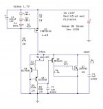
The appropriate schematic is in post #2.
Exact Q1 gate voltages for both regulators are ideal. Prepare two sets of LEDs with identical voltage drop of circa 5.1V. You can either take notes when testing every LED in your stack by testing them one by one. Or you could solder five strings of three series connected, and measure the joined voltage drop. Take the two nearest.
Have a bench power supply (or a full 9V battery) with a constant voltage, connect a series resistor and measure the voltage drop. Use Ohm's law to calculate the voltage and resistor values. 1.7V LEDs do 0.005A, if I'm right here.
If you want 50mA total current from your power supply you can have two regulators, each set for 25mA. 10-12mA would go to your 6J5 valve, the rest (15-13mA) will flow into Q3. This 1:1 relationship ensures good quality sonics.
Setting the current through the regulator is done by adjusting the value for R1. There's a calculation for the exact value but here's a shortcut. Be aware you're dealing with high voltage, so don't get electrocuted. Solder a 22 ohm resistor (0.5W or thicker) in series with a 100 ohm potentiometer (wire wound would be best) to replace R1. Measure the current flowing from your power supply to the regulator and adjust the potmeter until you see 25mA. Replace the resistance of 22R+potmeter with the next suitable value.
35V headroom is not much, maybe Salas has an advise for you on this matter. Current is modest and the (SE?) load is sort of constant, much depends on the stability of your power supply and mains behavior.
The output voltage is adjusted by turning R5 until you obtain the value you need. I noticed (on much higher dissipation) output voltage has the tendency to creep down in time. So, for final adjustment readjust R5 again after 10 minutes.
The power dissipated in Q1 is 215-180=35V@0.025A= 0.9W. A very small (sheet of cupper?) cooler is needed. Q2 on the other hand takes 180V@0.015A=2.7W. This one needs a finned aluminium heatsink. Something of 4x4x6cm could do the trick, take a bigger one to be on the safe side.
Enjoy!
Wonder if I could get some help too?
I have boards ("disco" type) for the regulator, and a 6j5G preamp running 10-12mA per channel. 180V on the anodes, LED bias, stepdown trafo output.
My Vin will be about 215V if I run a total of 50mA over my psu PI-filter.
It´s my best guess with some psud2 help anyway. I could get it higher, but I do not have much room for cooling so I think it is the best I can do. 50mA is max for the choke.
Concerning parts I have both green and red LEDs
Reds are Vf=1,7
Green are Vf=2,1
Both acording the data sheet.
Now- do I need to test the LEDs somehow before I can proceed, or is it possible to adapt the schematic based on this info.
Quick total answer.
 Use your reds, & one common shunt.
Attachments
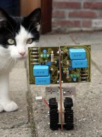
Nice and small! Cool kitten too.
The whole is on a 3mm copper plate and the Peltiers were ment to go outboard. Unless I run 12V @ 5A through each of them (!) they're not up to the job of cooling the 33W total mosfet dissipation. Currently I'm looking for a massive processor heatsink for the irf840 and cool passively. Better for the environment
Cool is not my discription for this living typhoon. Turbo is its name and sleep is not in the game

It's for a SE tube ampJaap, what kind of load do you intend to power with these regs? Voltage out, shunt current, load current, could you expand a bit on this? I'm curious because you're dissipating quite a bit of heat there.
bulb:stereo ). Overhead will be 50 volt (bad mains over here), current margin 50% (set for 90mA, 60mA to load). At first it will be operated at 300V output, finally at 325V. I've got a working prototype but heat is an issue, especially under the hood of the amplifier. At the rear of the case I left room for two lunky heatsinks, fiddling the parts in is a pain though
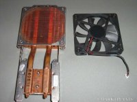
Low level noise would be tolerable but vibration is a nono. Got hold of this small unit from a notebook but I don't expect it to handle the 12W coming from the irf840...
http://www.youtube.com/watch?v=nC2gZMNkyJo
I have some 12x12cm fans which are very quiet. But yes, I do feel them moving if I keep them in my hand. If your case is open below (often the case with tube amps) there is the possibility of sitting the fan free of the case, below the case, lifted just a bit off the floor, located somewhat below the heat sinks, but not attached to them. I guess I'm stretching it now.
About constant current by depletion mode mosfets.It can be done. The particular P-Mosfet though proved stable and good for noise. Its a simple concept, it can easily be modified & implemented to suit different part inventories and precautions. That is the beauty of it. Build a tailor one and listen to it SY. Highly recommended.
LND150 is a nice part. I have seen this as part of a 24-230 V input for PLC.
http://www.supertex.com/pdf/datasheets/LND150.pdf
With a single part you have a current source capable of 500 V and a couple of mA's.
The circuits are easy to make. They are variable. I will show 2 voltage scales.
One more question:
In the following schematic
http://www.diyaudio.com/forums/attachment.php?attachmentid=121728&d=1229193814
Q2 BE junction seems paralleled to Q5 CE + Q4 BE.
ie
Q2Vbe = (Q5Vce + Q4Vbe) = 0.7V
Con you confirm that Q4 and Q5 are working in the linear region?
Regards
diy_audio_fo
About constant current by depletion mode mosfets.
LND150 is a nice part. I have seen this as part of a 24-230 V input for PLC.
http://www.supertex.com/pdf/datasheets/LND150.pdf
With a single part you have a current source capable of 500 V and a couple of mA's.
Thanks.
For those having 10M45S or DN2540 I recommend they give it a go. Don't know if it can alter something subjectively, these are parts that were not in my bin when I put it together, but are very practical for the CCS. I would like to see feedback from someone. If I will need a new one, I may try 10M45S that I got a couple now. So to know what happens first hand.
One more question:
In the following schematic
http://www.diyaudio.com/forums/attachment.php?attachmentid=121728&d=1229193814
Q2 BE junction seems paralleled to Q5 CE + Q4 BE.
ie
Q2Vbe = (Q5Vce + Q4Vbe) = 0.7V
Con you confirm that Q4 and Q5 are working in the linear region?
Regards
diy_audio_fo
Sorry, I am not an engineer, that question is over my head. I just put together that circuit after a quick idea one afternoon from parts in my bin and it sounded good to me for so few parts. It has some terrible erratic aspects most probably.

- Home
- Amplifiers
- Power Supplies
- Simplistic MosFET HV Shunt Regs