How many R3 have you used?
R3=56k with 330Vdc will pull 5.9mA each.
R1=47r with 2.3Vdc will pull 49mA
Leakage through C4 & C5 should be <<1mAdc. Did you reform them (slowly) before assembly?
Total draw will be ~5.9xN + 49 + 0.1 mA
If N = 1 then total secondary current is 54mA and your secondary current rating should be >>108mAac
I would select >=200mAac
If N=3, then >=260mAac
Note, that output current draw does not enter any of the calculation.
That is the way CCS fed Shunt Regulators work.
I have only one R3. This unit has been assembled in 2009 and I am working now on it to replace the 100VAC main transformers with 230V.
I am always a bit cautious to overrate the current of the HV secondaries as by experience I ended up with higher voltages, due to the regulation.
The transformer I am using has to serve the Salas regulator and the regulated filament (LD1084) for two 5687 or ECC182. With your estimate I would end up with two secondaries 250V@250mA and 7.5V@3A. I end up with a 100VA transformer that looks like suitable for a power amp rather than an IV stage.
The unit is a DAC-END 2 from Quancho, the AD1865 DAC.
Thanks,
Davide
Last edited:
Electrolytic capacitor current LEAKAGE
Capacitors leak current when exposed to voltage difference across the plates.
The manufacturers' datasheets will specify the maximum leakage for their types after a very short reform of 1 to 5minutes.
This usually takes the form of:
Maximum leakage current = 0.02CV
For a 220uF 450Vdc electrolytic operating at 400Vdc, that formula would give
Ileak = 0.02*0.00022*400 = 0.00176 = 1.76mAdc
But that is the maximum leakage of a good capacitor that has not reached the end of it's life and after a very short reform period.
In practice that leakage current varies enormously. At power ON the capacitor can leak massively until the insulating layer rebuilds on the surface of the plate/s.
After many minutes of applied voltage, the leakage should be much less than the specified maximum.
After a slow reform I have found that leakage current can be as low as 1% to 0.3% of the specified maxima.
I reform my electrolytics very slowly and reform them a second time, just as slowly, after a slow discharge.
This can be very important to "timing" capacitors that are fed with a low current through a high value resistor. Leakage here can destroy any sensible prediction of the timer period.
Very high voltage capacitors need to be reformed slowly to prevent damage at first power ON.
I use <1mA of charging current during reforming and typically around 0.2mA and then applied over a period 24hours till leakage is measured as very low.
Last edited:
You have to identify the individual currents and add them up.Beside the discussion on overrating the transformer, am I correct that with everything working properly, I should not see more than 60-70mA been drained by the transformer ?
Regards,
Davide
Have you checked the 56k R3 dissipation?
What is the voltage rating for the resistor you have used?
I suggest you use two or three resistors in series so that each sees a much lower voltage and a lower dissipation.
No, this assumption is wrong. Could you tell me the voltage just before the CCS? Ideally - mention also the value of R9 and the active resistance of the secondary.Beside the discussion on overrating the transformer, am I correct that with everything working properly, I should not see more than 60-70mA been drained by the transformer ?
The effect does not related to capacitors' leakage at all.
Last edited:
I have a 5H choke instead of R9. I think the resistance is about 70 ohm. By memory the voltage before the CSS is 294V.
Just to be clear, if my transformer is too small, I am fine with that, I'll just get a bigger one. What I do not want is to use a bigger transformer just to cope with a faulty behaviour of the circuit.
Thanks for the help.
Davide
Just to be clear, if my transformer is too small, I am fine with that, I'll just get a bigger one. What I do not want is to use a bigger transformer just to cope with a faulty behaviour of the circuit.
Thanks for the help.
Davide
It is possible to explain where is the rest of power go, but it seems the post will be rather long and off-topic here. But you can easily estimate a transformer needs by using PSU Designer II (http://www.duncanamps.com/psud2) or even easier - some info sheet from a transformer manufacturer (for example - https://www.hammfg.com/files/products/700/hammond-recitifier-guide.pdf).
In two words - The more voltage across the first capacitor you want the less time the diodes in rectifying part conduct every period of mains input, so the current in the transformer will be more like impulses with peaks of magnitude of the load current. It brings all sort of losses.
In two words - The more voltage across the first capacitor you want the less time the diodes in rectifying part conduct every period of mains input, so the current in the transformer will be more like impulses with peaks of magnitude of the load current. It brings all sort of losses.
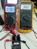
Just to be sure I did not forget anything - here is the simulation of the CCS part @ 70mA (the current which should be set according to the desired 50mA for the load).
The measurement at 70mA CCS current draw does not follow by large. It reads -1.66V for Q1 VGS & -1.58V for Q2 VGS. For non matched random DMOS.
Attachments
It can mean many things: unreliable datasheet values, forged parts, wide margins for "good" parts... I checked the SPICE model for DN2540 and it seems close to the Output and Saturation curves, but greatly differs from Transfer Characteristic curves, which in reality close to your actual readings. So mistakes in the datasheet are not improbably.
The installed parts I measured are genuine from Mouser. In any case the Q1 VGS will be Q2's VDS and it should read equal or greater than Q2's VGS. For practical purposes when checking a possible CCS parts failure in this circuit anything well bellow 1.5V VGS is suspicious and the suspect DMOS should be lifted and checked for IDSS alone. Also the gate Zeners may be dead or compromised already and better be replaced with new ones or substituted with 1N400X diodes in same orientation. If the root failure condition is uncertain, for better stability the gate resistors can be changed to 1K value (makes slower CCS but still very good)It can mean many things: unreliable datasheet values, forged parts, wide margins for "good" parts... I checked the SPICE model for DN2540 and it seems close to the Output and Saturation curves, but greatly differs from Transfer Characteristic curves, which in reality close to your actual readings. So mistakes in the datasheet are not improbably.
P.S. By measuring their IDSS you could use the one closer to 3-4mA if there is one in three like that but most samples would produce enough current to fit the main VR range.
How to easily measure IDSS
How to easily measure IDSS
Reproduction 2SK170
Don't know if anyone has mentioned yet but I just learned out that Linear Systems is making a reproduction of 2SK170 under the name LSK170. These would be high quality enough to be used in your regs as well?
http://www.linearsystems.com/assets/media/file/datasheets/LSK170.pdf
Don't know if anyone has mentioned yet but I just learned out that Linear Systems is making a reproduction of 2SK170 under the name LSK170. These would be high quality enough to be used in your regs as well?
http://www.linearsystems.com/assets/media/file/datasheets/LSK170.pdf
Yes its been around for some years and it is OK for low voltage regs mainly, like the DCB1 PSU and audio areas, there are families of IDSS available in the DIY audio store. It will perform driftier and with some extra IDSS to throw out in this one. But it can be used if necessary.
Series - Shunt
Dear Salas,
My friend has told me that the Welborne Labs PS3 acts like a very large reservoir in the power supply but not a "completely" and "high performing" regulator like the SSHV2.
I recently found the circuit of PS3 (see attachment)
Can we have a power supply build this way?
Full Wave Rectification (Cree Schottky Diode) --> 30uf --> PS3 --> 0.1uf --> SSHV2
Any comments? Do you recommended have a much larger cap instead of 0.1uf between the PS3 and SSHV2??
Thanks!
Attachments
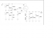
I would describe that circuit in the picture as a voltage referenced capacitance multiplier using a Mosfet. Your friend is correctly reading it.
Yes you could use that circuit as a pre-filter stage for SSHV2. Use 0.1uF as decoupler across SSHV2 input connector because there is already C106 // C107 as bypass output capacitance there. What are their values? Also Q1 will have to stand the voltage drop at SSHV2 current draw level so watch its sinking is adequate.
Yes you could use that circuit as a pre-filter stage for SSHV2. Use 0.1uF as decoupler across SSHV2 input connector because there is already C106 // C107 as bypass output capacitance there. What are their values? Also Q1 will have to stand the voltage drop at SSHV2 current draw level so watch its sinking is adequate.
Sorry!! Here is the parts list.
Resistors
R100,R101, R107,R108 220kohm 2W metal oxide
R103 8.2kohm 2W metal oxide
R104 10Mohm Roederstein 1/2W 1% metal film
R105 332ohm Roederstein 1/2W 1% metal film
Capacitors
C100,C101 100uf/450V Panasonic electrolytic capacitor
C103 1.0uf/630V Solen polypropylene capacitor
C104,C105 68uf/450V Panasonic electrolytic capacitor
C106 10.0uf/630V Solen polypropylene film capacitor
C107 .1uf/630V Solen polypropylene film capacitor
Semiconductors
Q1 2SK1511 MOSFET 1000V 5A
Z1,Z2 1N5378B 100V 5W zener diode
Z3, Z4 1N5383B 150V 5W zener diode
Z5 1N4742A 12V 1W zener diode
D16 1N4007 1000V 1A diode
- Home
- Amplifiers
- Power Supplies
- Simplistic MosFET HV Shunt Regs