Can the capacitors be too heavy kicking high spikes?
That's a real possibility so working with quanghao pcb
I left only 220uF psu & only 150uF reg: 47R + 220R + all LED's burned.
Changed 47R, 220R, all LED's, IRF9610 & SK170BL: LED's don't lit but when conect a 9V battery all LED's lit. After a moment powered the 220R gate resistor IRF9610 again burned also all LEDs burned
 .
.Now all testing with a dummy load 15K 10W connected, always 0Vout.
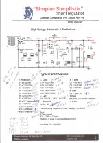
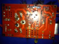
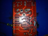
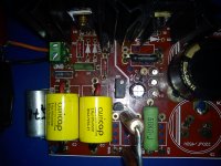
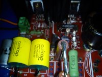
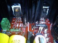
Attached quanghao schematic & some pics of the assembled board
Attachments
The LEDs should be OK. They are in series with R3 which limits the current.
I am not so sure what happens to Q4 during start up?
Similarly Q1 takes a big hit during start up.
I cannot see why the LEDs fail if you have assembled the circuit correctly. Did Q1 fail first and take out R1 and then bypassed R3?
I am not so sure what happens to Q4 during start up?
Similarly Q1 takes a big hit during start up.
I cannot see why the LEDs fail if you have assembled the circuit correctly. Did Q1 fail first and take out R1 and then bypassed R3?
Changed all semis + 56R adjust current resistor + 220R gate resistor IRF9610, LED's still don't lit, LED's tested with 9V battery and lit positive side connecting current adjust resistor and negative side connecting 100uF + 56K + 220R gate resistor IRF9610
Attachments
Merlin.
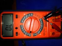
I think your have read your ohmmeter wrongly.
0.1 or 0.2 would indicate a short circuit.
0.L indicates overload. This is equivalent to open circuit, i.e. the screen cannot display a high enough value for the resistance it thinks it is measuring.
Thanks AndrewT,
I understood correctly that the resistor measured have a high impendance at least morethan my DVM can read so the resistor isn't shorted it's open without any contact so that's the reason my DVM can read.
Is R3 56K 5W? Measure Ohm across it with the reg off.
I did yesterday but I desolder again & read.
What voltage you can read across it, when the circuit is running? It must be Vin-3xLeds(~Vin-6V).
Across R3 56K?
With 15K dummy load or without dummy load?
R3 55K6
R4 119K5
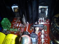
They look good. Is that black R1 OK? Can you put a simple metal film with short legs in its place? Did you check there is no continuity between fins and Mosfet tabs?
Across R3 56K?
With 15K dummy load or without dummy load?
Yes. But do the continuity and R1 checks before you fire it up.
The dummy load is to take pressure off the output sink and to evaluate heat near operating conditions in application. Since the voltages are high and the dissipation goes easily up, its good to have for heat share and to evaluate R1 so there is just enough extra mA for the reg to work fine above load need, and no heroic sinks. Usually +20-25mA. We use Ohm's law for a dummy near our real load need. So its helpful to have it there.
OK lets look back. You got two boards there, as I know well circulated and practiced boards. One red, one green board. Two different guys SSHV1 boards. You assemble by the book and they poof the same way. Had made one of those before? Worked? If yes, what changed in the configuration you plug them in now?
- Home
- Amplifiers
- Power Supplies
- Simplistic MosFET HV Shunt Regs