Not right at the input, say 15cm. First killed the oscillation with a 56ohm resistor and then tried a 47uF capacitor I had in hand. It was closer to pick up! Everything was with alligator clips and cables not twisted or anything.
It would be better at the input, but as I sorted it out, I did not investigate more.
It would be better at the input, but as I sorted it out, I did not investigate more.
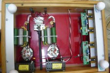
Power transformer 2x220V, 5R4GY rectifier, choke input ll1673, ll1660PP for output transformer and AVC from Intact audio.
Also got some nice BIG 10ohm 100W Dale resistor for filament bias.
Where did you bought the resistors?
King,
look at Salas posted pic.
2mA & 150Vce (or Vds) gives a dissipation of 300mW.
Find 300mW on the pic.
Draw a horizontal line at the 300mW height.
Where does the 300mW line cross the lower of the two plots? I'd guess about 115degC to 120degC.
The plot is telling you that at Ta ~115degC, the Tj = 150degC.
Now reduce Ta by 20C degrees to 95degC.
What is the new Tj? (answer, Tj=130degC)
Now reduce the Ta to what you estimate is the internal ambient temperature of the air around the regulator.
What is the estimated Tj?
If Tj < 100degC the device should survive long term.
If Tj < 70degC the device should never deteriorate in your lifetime.
- Home
- Amplifiers
- Power Supplies
- Simplistic MosFET HV Shunt Regs