Hi Chicco,
Don't get me wrong - I love to use passive attenuation wherever I can rather than introduce the extra complexity of active devices and their power supplies unless there is no other way.
In fact for my purpose I tried 10K pots to drive the amp (with 27Kinput R) but the same 1K and 1n filter as a quick simple lash up and to satisfy an immediate need (wife) to play music through it. But HF was not good at the volume setting she chose.
Worst case is at pot centre where 5K//5K = 2.5K source resistance adds to the 1k and results in the HF rolloff coming down to 45KHz (-3dB) . It dulled the sound.
Many amplifiers have an input filter. In my case the 1K matches the feedback input R leg to ground ensuring diff'l source Z balance for best CM behaviour. The C value could be smaller but 160KHz is reasonable and not nearly as low as some, especially low TIM designs, whose designers discovered that a severe input filter not only removed unwanted HF slewing problems with test signals but softened the top end - so you could hear the 'low TIM' difference.
Hi Carlos FM,
Appreciate your suggestion. But, if you saw the back of the board, you would find that the 100n small yellow C is connected +Vs to -Vs right there at pin 8 as well as the 2 x 10uF right at the other end of the chip near pin 4 (V-). If any more is ever needed there is an earth track right up the middle under the chip so a pair on monolithic 100nF could be added underneath right on the pins.
The other point is that the chip is operated in unity gain so has it's full PSRR and is less sensitive to PS quality than one with gain. For a similar preamp stage I would use my proprietary bootstrapped 2BJT 80 dB discrete regs as with the Bass Extender and Sub XO, albeit on a much larger board.
It was never meant to ever be more than a Simple Volume/Buffer.
Cheers,
Greg
amplifierguru said:If any more is ever needed there is an earth track right up the middle under the chip so a pair on monolithic 100nF could be added underneath right on the pins.
Aha, then put these in, and those 10uF caps are not needed.
Give it a listen, it's worth the trouble.
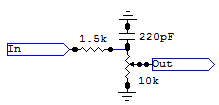
amplifierguru said:Worst case is at pot centre where 5K//5K = 2.5K source resistance adds to the 1k and results in the HF rolloff coming down to 45KHz (-3dB) . It dulled the sound.
That filter doesn't need to be after the pot.
Or does it?
This works very well:
Attachments
Ah Carlos,
We're down to the wire - but that's OK.
Yes on a wholistic approach the HF filter could indeed be almost anywhere. But the C also serves another purpose in it's current position, in my amplifier.
You see, the GB150D or SKA has the front end dual diff'l stage with single ended bootstrapped load R's and the input pair of complementary transistors of the dual comp diff'ls are doing some 80 dB+ of gain and need a very low base Z at UHF to ensure max GBW for the stage. And well defined, not variable. So that 1nF has to be there (but could be smaller).
Cheers,
Greg
Wow, talk about needing to calm down.
The thing with the little PCB for mounting output devices on waste material was a stroke of genius and a tip for us all. I was going to give kudos for it, but I didn't think it was worth the effort at the time.
Rule of thumb: more dissatisfied people will complain than happy people will compliment. If you have 10 unhappy one complains. If you have a hundred happy one compliments etc. Nobody is saying amplifierguru is not a valuable contributor, but every one has his own opinion.
MERRY CHRISTMAS TO ALL!
Greg,
If you go for more standard values like R-in 27k or 22k and C in-gnd of say 220-680pF, you wouldn’t have any practical HF rolloff.
About pot or attenuator, I always preferred 25K values instead 10K, maybe I just trying to escape from high frequency loss or whatever.
To be simple, I’ll tell you that I always experiment and listen. If it’s good for my ears, than it’s part of my audio system.
I agree about Carlos comments, PSU filtering is extremely important when dealing with op-amps, especially modern ones.
For the and, we may try to merge best of active and passive solutions in one!?!
HQ op-amp and good attenuator with good PSU. That’s interesting idea and we will all go in spirit of Christmas in solution which will suits all.
Once more, happy Christmas to all!
Chicco
Hi Chicco,
It seems you have not grasped my earlier reasoning. The amplifier, one of mine, has a typical input R of 27K in AC coupled mode matching the feedback R as is customary practice. The R=1K input filter R matches the feedback R to ground as is also good practice as it ensures equal source R for best common mode behaviour of the diff'l input stages. The C of 1n giving a input filter of 160KHz is on the heavy side of normal, but small compared with 'low TIM' mindset designs where 50KHz is common.
Placing a 10K pot in front of this is not good practice and gives clearly audible degradation. At worst cas this is a source of 2K5 and unbalances impedances and brings down the rolloff to 45KHz, clearly audible dulling.
As it was not only for my immediate needs but as a possible general solution exercise the values handled typify those in the field and it's a solution.
While an occasional specific pot/amp combination may achieve acceptable results an active solution, if well done, will always be a solution.
Cheers,
Greg
Tyimo said:Hi Greg!
Is it possible to get you PCB plan for this volume/buffer?
I know it is simple, but I like very much your design on the photo!
Greets:
Tyimo
Hi Tyimo
You can ask Greg this question at this site http://www.diyhifi.org/forums/viewforum.php?f=21
hope this helps
KL
amplifierguru said:I decided to do a small board for a volume control and OPA2134 dual FET cascode chip.......
Cheers,
Greg
Ideally, both ends of your pot. should be buffered; a dual op. amp. should do the job nicely.
Hi All!
After some years I finished the Volume Buffer!
Well, what should I say?!? It works very well!!!!
Basicaly I don't like chips or ICs and don't believe in buffers, but this small gear has super sound.
I tested with different power amps (ZV9, Profet, Aleph5) and sources (Marantz, Phillips, Yamaha CDPs) and also against some buffers (Musical Fidelity Nuvista, Pass B1) and it is better than the other buffers.
The sound is rich, transparent, detailed etc , but more holographic and mostly very good controlled.
Thanks to Greg for the help.
Greets:
Tyimo
I don't like chips or ICs and don't believe in buffers, but this small gear has super sound.
What have you built?
An IC powered chip buffer or something else?
I built Greg's Simple Volume Buffer Kit.What have you built?
It is an IC powered chip buffer with volume control.
I built Greg's Simple Volume Buffer Kit.
It is an IC powered chip buffer with volume control.
can you share the schematic?
- Status
- This old topic is closed. If you want to reopen this topic, contact a moderator using the "Report Post" button.
- Home
- Amplifiers
- Solid State
- Simple Volume/Buffer!