Just noticed that there seems to be some low level hash on the speaker line. On the scope it looks like RF hash from the power supply . But it could be just that my earth line isn't good. It increases when the tone is turned on. I put back all the covers but it's still there.
I was looking at the amp just now and found that one of the speakers ( B) has the output inductor on it.
So system A is a direct connection but system B has the R//L on the output. Didn't notice that earlier. It is in the manual, I missed it !
Still debating if I should just use a RC filter on the input stage or the capacitance multiplier. There is a huge difference in PSRR between the two but will it be so audible ? I like the RC filter as it has no additional active devices on it. Maybe I'll just try that first. DC protection would be useful too. The relays are already there for the speakers. Only need to add the protection section.
The output DC on the OPA2604 is below 1mV. The tone control however has something like 0.13 V on it's output. I tried shorting out the input cap on the power amp. From +60 mV the offset went to -24mV ! Tone was off.
So here is what I think one could do as a first step.
1. DC couple the power amp.
2. Leave all coupling caps on the tone stage so dc will not be a problem from there.
3. Remove the output coupling cap on the OPA 2604.
4. Change the input coupling cap on the OPA 2604 to a film cap.
5. Introduce dc protection.
6. Filters , RC or cap multiplier , on the power amp input stage.
Will have to be done in stages ! Will have to check this again to see if I've overlooked something somewhere.
I goofed seriously ! I opened up the amp again to implement some changes and discovered that all caps across the OPA2604 were already shorted out by small wire links. Didn't notice it earlier as they were so small and without insulation. I'd forgotten it was still there.
That must be why the bass was quite decent from what it used to be when new ! So all I had to do was short out the input cap of the power amp section. Did that and I get -24 mV offset at the speaker at all volume positions. Then I connected the DAC which must have a capacitor at it's output ! Some voltage would be there due to leakage current flowing through the volume control. So as the volume level went up the dc level shifted from -24mV at zero volume to -10 mV at max volume. That's great !
Now the whole amp ( minus the tone control ) is dc coupled ! Sounds great ! However I still feel the mids need to be a bit smoother though it is still very good. Possibly cleaning up the supply lines will help. So I have done item 1 , 2 and 3. Item 4 was not done as it's now dc coupled !
So now I have to do item 5 and 6 !
I love the bass. It goes so deep and tight ! Just right !
Item 5 is essential to protect the speakers in case something goes wrong or a source with high dc offset is connected! It will also protect the speakers in case anything else goes wrong in the amp. Burning a speaker is a major problem from both cost and parts and fixing point of view.
Item 6 will be interesting. Theoretically it makes a big difference in the PSRR. It will be interesting to see how much the difference will be in practice.
Need to play all the albums that I have been playing the past few days to determine how much better it sounds now. Voice certainly sounds better though I thought the sax was quite forward though it could be due to the recording. Will need to try out other albums.
The Tone control .
Coming to the 'bang' when the tone control is switched in. There is a plop but not very loud even with the volume up or down ! That should be reassuring . However when you switch in the tone control there is a slight step up in volume AND I think the sound quality drops ....like I'd say gets a bit noisy ! Will depend on the type of music. On voice it certainly sounds better with the tone switched out !
But it's very nice as it is and I am going to listen to it as it is for a few days before making any more changes. I'm happy I made all the changes.")
Warning to anyone who tries this. It's DC coupled all through and so you should have almost no dc coming from the source. To avoid such a death trap you could add a film cap of 1uF or 2.2uF at the input of the OPA2604. That way you are safe. BUT it now means the cap 'might' take away something from the sound ? Try it. In my case I think the HF sounds cleaner than earlier .....more airy specially the cymbals ! I guess this can be done to the RA-931 also. But it has no speaker protection relay and so you can't add dc protection easily. You could add a relay on a separate pc board.
That must be why the bass was quite decent from what it used to be when new ! So all I had to do was short out the input cap of the power amp section. Did that and I get -24 mV offset at the speaker at all volume positions. Then I connected the DAC which must have a capacitor at it's output ! Some voltage would be there due to leakage current flowing through the volume control. So as the volume level went up the dc level shifted from -24mV at zero volume to -10 mV at max volume. That's great !
Now the whole amp ( minus the tone control ) is dc coupled ! Sounds great ! However I still feel the mids need to be a bit smoother though it is still very good. Possibly cleaning up the supply lines will help. So I have done item 1 , 2 and 3. Item 4 was not done as it's now dc coupled !
So now I have to do item 5 and 6 !
I love the bass. It goes so deep and tight ! Just right !
Item 5 is essential to protect the speakers in case something goes wrong or a source with high dc offset is connected! It will also protect the speakers in case anything else goes wrong in the amp. Burning a speaker is a major problem from both cost and parts and fixing point of view.
Item 6 will be interesting. Theoretically it makes a big difference in the PSRR. It will be interesting to see how much the difference will be in practice.
Need to play all the albums that I have been playing the past few days to determine how much better it sounds now. Voice certainly sounds better though I thought the sax was quite forward though it could be due to the recording. Will need to try out other albums.
The Tone control .
Coming to the 'bang' when the tone control is switched in. There is a plop but not very loud even with the volume up or down ! That should be reassuring . However when you switch in the tone control there is a slight step up in volume AND I think the sound quality drops ....like I'd say gets a bit noisy ! Will depend on the type of music. On voice it certainly sounds better with the tone switched out !
But it's very nice as it is and I am going to listen to it as it is for a few days before making any more changes. I'm happy I made all the changes.
Warning to anyone who tries this. It's DC coupled all through and so you should have almost no dc coming from the source. To avoid such a death trap you could add a film cap of 1uF or 2.2uF at the input of the OPA2604. That way you are safe. BUT it now means the cap 'might' take away something from the sound ? Try it. In my case I think the HF sounds cleaner than earlier .....more airy specially the cymbals ! I guess this can be done to the RA-931 also. But it has no speaker protection relay and so you can't add dc protection easily. You could add a relay on a separate pc board.
Last edited:
That sounds like you should perhaps first try to contact clean all switches/pots?
Problem sorted, it was the speaker relay that needed cleaning
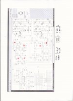
Details of the caps
I changed the capacitors around the IC 502 / OPA 2604 ( C501 /C502 and C515 and C516 )and the input cap of the power amp ( C601 and C602 ).
All were shorted across with a small wire. You can remove it later if you want to.
In my case I had planned to use a 2.2uF or 1 uF film cap at C501 and C502 ( input caps for OPA2604) so that no dc would enter accidentally. Protects the speakers from accidental dc due to a bad signal source. If you are careless then you should add these caps.
Attachments
I will make the dc protection circuit since I tend to keep switching sources and do not check all sources for their output dc offset. That could lead to destruction of the speakers ! The dc protect will take care of it.
But more importantly I will try out the supply line filtering. I want to stick to the RC filtering just because it's easier to do. But I'll make a plugable board to the main board so that I can plug in or out a RC version or Cap multiplier.
A three pin connector should do. Will now have to see where I can install this. Will have jumper wires from the bottom for sure. Things might look ugly under the board !
I'll decide this later. Want to minimise doing anything physical to the board.
Many Rotel amps don't seem to have any speaker protection except a fuse. Few have relays too. I also find the older amps don't have the L//R combination at the output. My RA-01 has it for one pair of speakers. The RA-970BX doesn't have it in either speaker line. Looks like the 970 can also have many caps removed ! However I feel safer if they all have relay protection in case something does go wrong ! Can't afford a blown speaker !
I changed the capacitors around the IC 502 / OPA 2604 ( C501 /C502 and C515 and C516 )and the input cap of the power amp ( C601 and C602 ).
All were shorted across with a small wire. You can remove it later if you want to.
In my case I had planned to use a 2.2uF or 1 uF film cap at C501 and C502 ( input caps for OPA2604) so that no dc would enter accidentally. Protects the speakers from accidental dc due to a bad signal source. If you are careless then you should add these caps.
The description in your schematics photo is different with what you say.
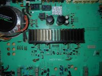
You must have removed C501,C502,C515,C516 and replaced C601 and C602 with 2.2uF or 1uF (that's shown in the photo of the actual modded amp you post earlier)
Can you check it?
The description in your schematics photo is different with what you say.
You must have removed C501,C502,C515,C516 and replaced C601 and C602 with 2.2uF or 1uF (that's shown in the photo of the actual modded amp you post earlier)
Can you check it?
No, my last post is correct.
The photo is BEFORE I removed the films caps (C601/C602....2.2uF film) which I had added earlier to the power amp to replace the electrolytic that was there.Done long ago.
Now there are NO caps at all the positions indicated.
The suggestion to use a film cap at the input of the amp ( C501 and C502) was for those who are not sure of the dc offset of their source and for those who just wanted to be careful with different sources.
I do not use a cap at C501 or C502 ! I've checked all my sources and their dc offset is negligible. No one else would use this amp so it's OK for me to do this.
Last edited:
Also remember NOT to connect the speakers when you first switch on after making the mods.
Use a DMM to check the output dc voltage on BOTH channels at the speaker sockets.
If it's less than +/- 0.1V ( 100mV ) all should be well. Remember to switch the speakers ON with the switch on the front panel !
I've worked on a dc protection circuit that can be added to the existing relay and it's driver transistor. It needs five connections.
1. The +12 V supply.
2. The driver transistor +12 v supply point.
3. Ground
4. L Ch speaker output
5. R ch speaker output
It can pass through a 20 Hz sinewave at maximum voltage ( I used 36 v peak which is higher than is really possible !).
Tripping at a ( not too bad! ) 2 V dc offset is less than 1 second. At higher voltages like 10 V dc it trips in less than 0.5 sec.
I'll have to make a pcb and test it out. Certainly should be done by this weekend.
Attachments
Last edited:
Looks like a small change in the supply line will help us put in an LED to show when the circuit has tripped due to a dc fault. I guess I'll have to build the board to see how well this works.
The board is about 1.25 x 1.5 inches in size. ( about 30x35 mm !) Any comments on the protection circuit are welcome. Would like to fix any inadvertent errors and maybe reduce parts count and board size ! I've used fairly large pads and traces so that they will not lift off if I have to solder/desolder parts several times.
The board is about 1.25 x 1.5 inches in size. ( about 30x35 mm !) Any comments on the protection circuit are welcome. Would like to fix any inadvertent errors and maybe reduce parts count and board size ! I've used fairly large pads and traces so that they will not lift off if I have to solder/desolder parts several times.
I find that one can fix the board easily using the chassis earthing screw right next to the bridge rectifier. I've placed a printout of the board to indicate the size. This is just above two fuses and may not be an ideal position.
Mounting it to that grounding screw means that maybe one wire connection can be reduced. So we need four more wires. 2 for the speaker lines and two for the power in and power out ( 12 V dc ). Can route it near the real panel and down through the gap near the transformer and then below the board and soldered to the correct places. Only hack is to cut the 12V track that goes to the relay driver transistors. Can use a small length of Cat 5 cable for this ! Will look neat too.
Will be opening up the RA970BX this weekend to see what I had done to it earlier ! I do remember that when I was fiddling with these two Rotel amps long ago I didn't have the service manual. But some schematic or part of it must have been there I think. I can't really recall. The gray cells must be dying !
Attachments
Last edited:
Two setbacks. One is if I redesigned the protection pcb it will be easier to install and wire it. So I'll do that.
I opened my RA970BX and found that I had bypassed the input line stage and tone control and directly wired the power amp input to the volume control. The input cap is still there. DC offset on one channel is 70 mV and on the other channel is 1.12 V ! Something wrong there. So the amp goes back into storage till I have enough time to fix that ! I have plenty of other work to do . Not worth wasting time fixing the 970 just now. I was really keen on hearing it today !
The 970 BX is very poorly designed. The bottom plate is plastic ! So no metal shielding for the bottom of the pcb ! All the glue they used to hold the capacitors have become a mess and have cracked off also. But then it's an old amp. Though some other older amps seem to be doing not too bad compared to the 970.
Last edited:
I shorted C601,C602,C515 and C516.
DC offset indeed dropped to -24mV (from 43mV).
I noticed the "bang" sound when you switch the tone control but it's almost inaudible.
Sound wise i think it took away some of the Rotel harshness and yes the bass is tighter than before.
I think so far these mods are safe regarding amp's stability, what do you think?
Any other changes before i put the lid back on?
Cheers
An externally hosted image should be here but it was not working when we last tested it.
You are doing fine. I think the next step before anything else is to add the dc protection. I will try to have it ready today. So In case any more fiddling causes any dc in the output it will protect your speakers which is currently only protected by a fuse. As it is the unit should be quite stable.
Just be cautious about your source ( if you change it ). Connect it and measure the dc at the amp output without speakers connected. Turn up the volume as it acts as a voltage divider and any dc from the source will also get divided. I check for dc with the source connected ( music on pause) and volume at maximum and no speakers connected. Remember that setting the switch to speakers 'off' will disconnect the speaker terminals from the amp !
I'm redesigning the protection pcb so that it fits easily and can be wired very easily.
Till the next step, listen to your favourite music and see how much better the sound is !
Last edited:
RA970BX circuit diagram errors in the service manual
I found two errors in the circuit diagram . At first I didn't understand how the negative feedback worked. It appeared that the circuit had two connections that should not be there. The resistor between the driver emitters and resistor between emitters of pre drivers should generally not be connected anywhere else. On the circuit diagram they are connected to the NFB resistor coming from the output. This is wrong. So I checked this on the board and there this connection is not there. It is connected the correct way ( ie. not connected to the NFB resistor )
So anyone trouble shooting the circuit should take this into account.
Yes, and the base to collector shorts to the rails on Q619/20/21/22 are most probably not there either.I found two errors in the circuit diagram .
If they were, the only sound you would hear from this amp would be the sizzling of the remains of the burnt output stages.
As for the DC offset on the output, that is probably caused by the unknown DC loading of the input transistor bases by direct coupling them to the volume pot.
In fact, you may be able to null it by adjusting the volume and/or the balance knobs?
But it will change again when you connect a source to the amp input. I would recommend that you keep a high quality film cap as in your RA-01.
Cheers,
Per
- Status
- This old topic is closed. If you want to reopen this topic, contact a moderator using the "Report Post" button.
- Home
- Amplifiers
- Solid State
- Simple upgrade for Rotel RA-01 amp..