P { margin-bottom: 0.08in; } Hi, I need a little help building a basic (active) tone control for my amplifier based on TDA1552. I'm looking for a circuit diagram and I need to know exactly where it's built into the amp (before or after volume control). What I've found so far......Hi-Fi Preamplifier (s. Attach) uses opamp TL072 which in turn uses a dual power supply, whereas I only have a single +15 Volt line. Is anybody familiar with the circuit (recommendations, advice)? or could anybody recommend similar please? If you can help, much obliged, if you can't, please don't suggest a Google search.
Attachments
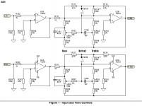
At the junction of R101/2 and R202/2 place a 4u7 capacitor with the +ve end on the junction. This will now become the inputs. They will allow for a raised 0v.
Where the downward pointing arrows are; 0v on this circuit, connect the junction of two 10k resistors with a 100uF capacitor to what is shown as the -ve rail and use the two resistors as a voltage divider between +ve and -ve.
You can now run with a single rail..
Fit another 4u7 capacitor on the outputs of the op amp to decouple the outputs and they will then become ground, voltage wise.
At the junction of R101/2 and R202/2 place a 4u7 capacitor with the +ve end on the junction. This will now become the inputs. They will allow for a raised 0v.
Where the downward pointing arrows are; 0v on this circuit, connect the junction of two 10k resistors with a 100uF capacitor to what is shown as the -ve rail and use the two resistors as a voltage divider between +ve and -ve.
You can now run with a single rail..
Fit another 4u7 capacitor on the outputs of the op amp to decouple the outputs and they will then become ground, voltage wise.
P { margin-bottom: 0.08in; } I don't fully understand....can you check Attach please? When you say „this will now become the inputs“, does that mean no input to pin 6? Are all caps eletro? Should the voltage divider R*s really be 5Watts....its only preamp stage. And lastly,,,,I presume the two pots are ganged log?
Sorry

Attachments
connect the junction of two 10k resistors with a 100uF capacitor to what is shown as the -ve rail
By "-ve rail" here, aren't you rather referring to the inverting input? Otherwise, sorry, it doesn't quite make sense. An appropriate modification to what I've already drawn (previous Attach) would make things soooo much clearer. Anybody?
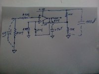
Perhaps this will clarify the circuit that you need.
The two 10k 1/4watt resistors provide a 1/2 supply reference for the op-amp inputs thus doing away with the need for a separate +ve and -ve supply.
Thus if you have 15V supply then the amplifiers have a +7.5V and - 7.5V supply with respect to their inputs.
A coupling capacitor is now required at the each input as shown to remove the 1/2 supply offset as the input is no longer referenced to 0V. The same applies to the outputs
Last edited:
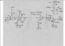
here is an overview.
the volume control can be attached at the output as shown.......
or at the input instead of R1.
the -inv input ( opamp1) can be connected to 7,5V as shown in post above ....
or with a cap in series to ground.
the part dimensions are suggestions,not carved into stone.
the volume control can be attached at the output as shown.......
or at the input instead of R1.
the -inv input ( opamp1) can be connected to 7,5V as shown in post above ....
or with a cap in series to ground.
the part dimensions are suggestions,not carved into stone.
Attachments
.......post 23 in this thread.......schematic on principle
http://www.diyaudio.com/forums/solid-state/177879-transistor-tone-control-schematic-3.html
http://www.diyaudio.com/forums/solid-state/177879-transistor-tone-control-schematic-3.html
The 10 ohm resistors serve no purpose and can be shorted. As the tone stage is inverting I can't understand why the buffer has been configured as non inverting gain stage rather than inverting to correct the phase issue. Uses less parts, and has the potential for better sonics.
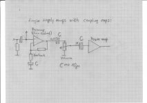
Don't forget the outputs are at half supply and need AC coupling.
Don't forget the outputs are at half supply and need AC coupling.
Don't forget the outputs are at half supply and need AC coupling.
P { margin-bottom: 0.08in; } Is this capacitive coupling? Could somebody explain please as I need to feed this to the next stage...power-amp via volume control/balance.
P { margin-bottom: 0.08in; } Is this capacitive coupling? Could somebody explain please as I need to feed this to the next stage...power-amp via volume control/balance.
The output of the final opamps should be fed to the volume control via a cap. Somewhere around 10uf will allow for any volume control value to be used. Positive end of cap to the opamp.
- Status
- This old topic is closed. If you want to reopen this topic, contact a moderator using the "Report Post" button.
- Home
- Amplifiers
- Chip Amps
- Simple tone control question