Hi mooly.
Thank you. I'll keep it in mind.
Hi ashok.
I judge by behavior, not history, my country taught me this. In diyaudio, LC, AKSA, PASS are my gurus for their unconditional kindness towards the young people. And I feel lucky to have them here.
Anyways, I am out of boards so will connect the servo hanging there.")
Thank you. I'll keep it in mind.
Hi ashok.
I judge by behavior, not history, my country taught me this. In diyaudio, LC, AKSA, PASS are my gurus for their unconditional kindness towards the young people. And I feel lucky to have them here.
Anyways, I am out of boards so will connect the servo hanging there.
Let look at the things on a cool way.
What is the offset problem ? It can dangerous four our speakers, and it is not good for the sound (signal no more symmetrical).
What can be the cause of the problem ? DC voltages applied at the amp input, or generated inside-it by components disparities, temperature effects, or failure of some component inside-it.
What are the solutions to get rid of that ?
A- Build the amp in such a way that it will produce minimal offset (paired parts, thermal coupling)
B- Reduce the amp gain at DC to 1 (cap in the return path of the feedback to ground for the FB level is 100% at DC),
C- Servo, witch auto compensate any (little) DC in applying a DC in the opposite side.
D- Protection circuit, to disconnect Loudspeakers if any DC present at the output of the amp.
Everybody here knows the advantages and disadvantages of each solution. No one is perfect and resolve all situations and cases.
Even the one chosen by L.C., the only one to have no negative impact on the sound, present disadvantages: Pairing parts require you have a great number of them, and complicate your buying process.
So there is no moral about choosing one or several solutions depending of your needs and situation. And the accurate answer will not be the same if you are rich or poor, a manufacturer aware of SAV returns, manager of a PA system, DIYer, his mother in law or an audiophile playing little samples of music and listening to his equipment instead of the music.
The only thing is for sure, if you want to protect your speakers, use an appropriate fast protection circuit (with as minimal negative effects on the sound as you can), AND as Shaan, evaluate the negative effect of an electrochemical condenser in the signal path and compare with the one of a servo, chose the solution you prefer... OR none of them.
If you can, apply the LC methods, as nothing can be better for the sound, and consider any added solution (protection circuit, condenser in the FB loop, servo etc.) as an external protection circuit.
Reading the RNMarsh's remark, my thoughts were: "What is this guy problem ?", and i had a smile as, from the beginning of this thread, the SSA amp was, of course, presented with no servo in his basic concept.
In that matter, there is no Guru as there is no religion
On my side, and on my SSA modified Crescendo, it was impossible to apply the clever L.C. practices. The circuit was yet done, components not paired, and not thermally coupled. So, of course, i had considered adding a servo, but, at the end i had chose to add a simple cap, for a reason witch not brooks any criticism: I'm more Lazy than audiophile.
Last edited:
From you web site, this sentence:can you design circuits which do not require a dc servo? -RNM
The signal path is "direct-coupled" from input to output for music signal purity, employing Richard Marsh's popularized concept of Servo-Control
plunged me into an abyss of confusion.
I would like to add few thoughts:
... A servo add a benefit comparing to a cap in the FB return path to ground: It can compensate DC while Cap only reduce-it, with regard to the signal level, by the gain factor of the amp.
... A servo will add noise (depending to the noise factor of the OP), cap will add non linearity and slight HF level reduction due to its inductance. Both will add phase turns in low frequencies.
... Because, in a servo, there is a cap too in his FB signal path, we can chose a lower cutoff frequency if we want to minimize its sonic influence in the audio bandwidth.
... But we can consider that the non linearity of the cap impedance in the audio bandwidth is negligible, considering the high impedance we can set, using OP with fets input devices (we will try to use film cap).
... While the low impedance of the feedback loop oblige us to use huge electrochemical capacitor values.
... In the SSA, we are in the best situation to use a polarized caps, as the two symmetrical branches of the feedback are polarized at >+0.7V. & <-0.7V, in most of the schematics (with NPN+PNP input transistors) .
... It seems (to my ears) that the bad sonic influence of the electrochemical cap is less obvious there than some in serial with the signal.
On a more general point of view, and according to a French proverb, there is no way to have in the same time: butter, butter money, and the smile of the dairy.
For me the reasons for trying a servo as shown are very simple.
1. I want the offset nulling to be automatic, not needing manual trimming.
2. An input cap is okay, and I know how to eliminate the VLF gain, and it's easy.
3. The servo and the regulated PS circuitry aren't costly and not complex.
4. My previous experiments didn't show any bad behavior from it.
1. I want the offset nulling to be automatic, not needing manual trimming.
2. An input cap is okay, and I know how to eliminate the VLF gain, and it's easy.
3. The servo and the regulated PS circuitry aren't costly and not complex.
4. My previous experiments didn't show any bad behavior from it.
Hi Shaan/LC
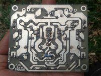
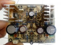
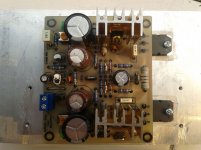
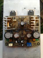
I've finished my build today.
Before i powered up this Amp, please guide me how set dc offset, bias and anything i should care.
Thank you.
I've finished my build today.
Before i powered up this Amp, please guide me how set dc offset, bias and anything i should care.
Thank you.
Attachments
Hi Shaan/LC
I've finished my build today.
Before i powered up this Amp, please guide me how set dc offset, bias and anything i should care.
Thank you.
Hi naf

First time powering demands some steps:
- short the input with piece of wire
- connect 47 ohm/5-10 W resistors in series with +/- supply wires. That will protect your SSA amp if something is not correct or against oscillation damage. If everything will go OK, you will have cca. 4,7 V voltage drop on these resistors at 100 mA bias current.
- both trimmers should be set to max resistance before powering up
- connect DC V-meter (set to min range) between +OUT and GND
- also use second DC mV-meter to control the voltage drop on 47 ohms resistor at + rails wire
- power up the SSA and than slowly increase the current by turning the trimmers in a way that output voltage is always around zero DC. This is performed by setting-rotating the trimmers separately, first one, than another, than first ... and so on
- if all is OK with raising current up to 100 mA (4,7 V voltage drop) than you can connect SSA directly to power supply and set proper bias current. At this point use 3-5 A fuses on 47 ohm resistors location.
- output DC should be in a range of +/- 50 mV
- if you don't have the scope than 12 V/5W bulb will show you that there is no oscillation at output, simply by not lit at all
- unshort the input and connect the signal
After using SSA for some time, these fuses can be replaced with stronger ones ie. 10 A or removed completely.
That's about all.
Thank you LC,
i've followed your guide and, i got my dc offset unstable, the best i can get is -33 mV but it's hold no longer than 1 minute and keep changing.
i use 10 ohm/10W resistor on + rail and my second DMM read 320mV.
is there any tip to stabilized my offset?
Thank you.
i've followed your guide and, i got my dc offset unstable, the best i can get is -33 mV but it's hold no longer than 1 minute and keep changing.
i use 10 ohm/10W resistor on + rail and my second DMM read 320mV.
is there any tip to stabilized my offset?
Thank you.
With 10 ohm, V drop has to be between 1V and 1.5 V (100 -> 150ma)Thank you LC,
i've followed your guide and, i got my dc offset unstable, the best i can get is -33 mV but it's hold no longer than 1 minute and keep changing.
i use 10 ohm/10W resistor on + rail and my second DMM read 320mV.
is there any tip to stabilized my offset?
Thank you.
once set, and offset roughly minimized, close your rack, and let the amp heat for at least 20mn to let temp stabilize inside. Then carefull tune again your offset (as fast as possible)..
It is normal than your offset rock'nroll, and +-33mv is something you can consider as null.
Thank you LC,
i've followed your guide and, i got my dc offset unstable, the best i can get is -33 mV but it's hold no longer than 1 minute and keep changing.
i use 10 ohm/10W resistor on + rail and my second DMM read 320mV.
is there any tip to stabilized my offset?
Thank you.
By rotating the trimmers, you actually change input stage bias, so you should get + V or - V at the output, not just mV, you can rotate one trimmer strongly and you will get let say + 10 V on the output.
So if your output DC voltage-potential is only negative - V, that means something is not working.
Please remove 10 ohm resistor and connect two 47 ohm/5 W on both rails, since these resistors are not there for measuring purposes but for protection against failure.
Whan you will have app. 0V at output, 100 mA supply current (4,7 V voltage drop) and no oscillation, than and only than you can remove 47 ohm resistors and connect SSA to power supply directly.
Please check the schematic vs. PCB and parts values. Good luck
Hi naf.
About the pots, when you see the offset is increasing when turning one of the pots from maximum resistance then turn it back to its maximum resistance again and then turn the other pot, this will ensure a successful zero offset setting.
Also, if the output doesn't drift equally to +ve and -ve as you turn the pots then it means one of the input BJTs is under-biased and is unable to control the VAS at its collector due to lack of enough current through that input BJT. You can check the voltage at the 22ohm at the emitters of each input BJT and have a reading of at least 66mV for an input bias of 3mA; if less than this then the output might be stuck to only one polarity as the NPN and PNP input BJTs have different electrical characteristics.
To increase bias at the inputs you need to decrease the 1K2 resistors, which may need to be decreased to 1K or less for good bias of the inputs. The easiest way to do this is to parallel one 22K resistor with each 1K2 and test the input bias at the 22ohm resistor. If paralleling one doesn't make it more than 66mV at the 22ohm resistors then place another 22K with each 1K2 and check again. This way you will safely reach more than 3mA of input bias and the offset will then be symmetrical and easy to set to zero.
WUUUUUU HUUUUUU..


 , i'm pretty sure i'll hear the sonic of SSA tomorrow, it's late night so i can't test the sonic...
here what i've got.
DC offset 0.3 - 3.9 mV
stable bias at 198 mA
vas current 340 mV at 22r
THANK YOU SHAAN, LAZY CAT, ESPERADO for supprot and help, hope more newbie will build this AMP.
, i'm pretty sure i'll hear the sonic of SSA tomorrow, it's late night so i can't test the sonic...here what i've got.
DC offset 0.3 - 3.9 mV
stable bias at 198 mA
vas current 340 mV at 22r
THANK YOU SHAAN, LAZY CAT, ESPERADO for supprot and help, hope more newbie will build this AMP.
Last edited:
An externally hosted image should be here but it was not working when we last tested it.
All the best naf.
WUUUUUU HUUUUUU..
here what i've got.
DC offset 0.3 - 3.9 mV
stable bias at 198 mA
vas current 340 mV at 22r
THANK YOU SHAAN, LAZY CAT, ESPERADO for supprot and help, hope more newbie will build this AMP.
Yes, it's very nice when amp shows cooperation.

I wish you great enjoyment time by listening music tomorrow.
Congratulation.here what i've got.
DC offset 0.3 - 3.9 mV
stable bias at 198 mA
If your amp does not heat too much, and once burned out a little, you can try to reduce the bias of each power unit to 150ma. Not sure for yours, but most of the power Fet/Mostfets i know seems to sound the best around this value in class Ab amps.
Now, if somebody ask-you if you can build an amp with no servo, you can just answer:
"Yes, I can".

Last edited:
HA HA HA, I'm the first newbie and unexperienced person who build this SSA Shaan's version.
This is my first CFB and FET Amp!
Super, so also newbie can do it hehehe
What's the loudspeakers you have to connect to SSA?
If somebody ask-you if you can build an amp with no servo, you can just answer:
"Yes, I can".
I should have done that too...

I will, from now on.
Thanks.
- Status
- This old topic is closed. If you want to reopen this topic, contact a moderator using the "Report Post" button.
- Home
- Amplifiers
- Solid State
- Simple Symetrical Amplifier