My layout on my mind
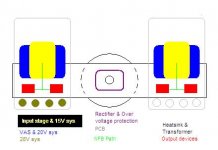
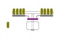
The attached is my new idea (1 piece per channel). Its a bit too plain so i think i will explain some of it. 1st picture is top view, 2nd picture is rear view.
The colours are quite apparent, so i will skip that part (sections). About the positioning, the transformer fix at same level with the circuit seems will affect one side of OPS, so i will adjust it lower, at the same level putting rectifiers and some varistor for protection purpose. This should reduce problem with transformer, but will the rectifier affected by its central field ?
My heatsink its a bit special, which is "originally" intended for Power LED. It is extruded fin type, so it had to face up and top of those circuitry.
Attachments
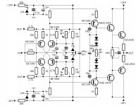
It looks like u have a long distance between your o/p stages & input/VAS.
Best to have all tracks between all stages as short as is possible and also feedback path as short as is possible.
if you want some distance somewhere then perhaps think about putting your diode board on the other side of your heatsink so that the sink acts as a screen - heaksink need to be earthed anyway.
That depends on actual circuit layout, so I'm on it now.It looks like u have a long distance between your o/p stages & input/VAS.
Best to have all tracks between all stages as short as is possible and also feedback path as short as is possible.
if you want some distance somewhere then perhaps think about putting your diode board on the other side of your heatsink so that the sink acts as a screen - heaksink need to be earthed anyway.
I'm thinking of making something similar to Lazycat's design, but different its that my board will be single sided, flipped upside down (LC's board to side) due to heatsink requirement. So I guess it needs alot of mechanical support for the board.(screws, bolts, etc)
The gap between board underside (copper path circuits) and heatsink about 7mm, is that sufficient ?
Does big capacitors (reservoir) acts as a shield against transformer influence ?
If I were to add a LED in my circuit (in a easy way without complication) to show its "life signal", where could I add ?
Attachments
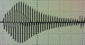
Yes. In our R&D office we used to keep for fun all the assemblies witch produced strange plots or amazing sounds. A sort of electronic horror museum. We had inaugurated this museum during a famous open house day ;-)Anyone some comments about this plot?
Anyone some comments about this plot?
This is typical plot of ...
P.S. Isn't the forum purpose also an educational one. This plot should be well known to younger DIY-ers to understand basics of an amplifier making.
Last edited:
Nah, just means a Turbo(t) amplifier.
Nope, you will be surprised ...

Nah, just means a Turbo(t) amplifier.

Attachments

Hi guys
Anyone some comments about this plot?
P.S. Fish in the scope?
Looks like on the edge ( of the sea If you ask the viking Hagar) of oscillations.
Does input cable cross outputwires?
Attachments

Last edited:
Your opinion about this waveform?
the sample of moog synthetizer wave?honestly I do not know
Ok:
1) switchemode in idle.
2) bridge rectifiers oscillating.
3) Relay coil
4) RFID reader pulse on/off
Which one will it be than?
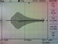
The timebase and frequence.
Tells me that we are talking softstart circuit.
The oscillation represent the current (Which has a frequence of 50Hz).
You will see the current build up to certain level (PTC heating up?) and the current will start falling as we get closer to the rectified voltage the capacitor bank will settle on.
Tells me that we are talking softstart circuit.
The oscillation represent the current (Which has a frequence of 50Hz).
You will see the current build up to certain level (PTC heating up?) and the current will start falling as we get closer to the rectified voltage the capacitor bank will settle on.
- Status
- This old topic is closed. If you want to reopen this topic, contact a moderator using the "Report Post" button.
- Home
- Amplifiers
- Solid State
- Simple Symetrical Amplifier