WOW !!!Hi guys, me back
LC, i had a shock, looking at your pictures, before to see you where the author.
Amazing realization, pure beauty and intelligence. Compactness, ease for maintenance, and wonderful design...
Even the free space behind the heatsink is perfect for air circulation.
What is the area where you're just good?
Hi guys, me back
I really like the simplicitiy of the input stage and splitted feedback and all about SSA, so I decided to solve thermal stability issue in a simple manner. Of course one could do it by adding BJT's, OP amps, etc., but than this would become something else. The simplest solution of them all is to put NTC + serial resistor in parallel to 100 uF in feedback bridge. NTC must be thermally coupled with the input pair BJT-s and serial resistor is serving to lock the NTC to be in exact proportion to input's Vbe thermal drift. At the end VAS bias current is stabilized to 10 mA from cold start to any thermal condition there is.
And some pictures to show how SSA BIGBT HP should look at the end.
Compact layout. But looks also easy to take apart if needed.
LC, they are really neat and nice. Whats more perfect is symmetrical ^.^ (suits as Complex Symmetrical Amplifier)
Edit : I'm interested to know the value, properties of the component for thermal stability issue (thermistor, resistor). Hope you can draw a diagram of connections too. (kinda blur where to connect)
Edit : I'm interested to know the value, properties of the component for thermal stability issue (thermistor, resistor). Hope you can draw a diagram of connections too. (kinda blur where to connect)
Last edited:
LC, the one you had just built is accordance to ?
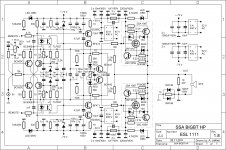
I'm curious what is the thing at output speaker (right side), which consist 2 diodes & resistor to input ground, and the 10 ohm with 100nF cap ?
What is the meaning of 100k to ground after VAS ?
What is the terminal "remote" connects to ? What is the TLP627 use for ?
You use different transformers in schematic, is to prevent ripple go into small signal stage ?
I'm thinking of cascoding my VAS too, but is the criteria for it ? Is BD139/140 sufficient ?
Attachments
Guys, for Cdom, what type of capacitor is best for use ? I attached some link, could you help me see which is better ? My ampifier's destiny lies in your hand !
10pF : -
(I) Buy Plastic Film Capacitor,tubular foil polystyrene,axial lead,160Vdc,10pF RS FSC 10PF 1PF 160V online from RS for next day delivery.
(II) Buy Mica Capacitor,silver mica,500Vdc,10pF RS D1510/500V online from RS for next day delivery.
(III) http://malaysia.rs-online.com/web/p/mica/2508362343/
(IV) Buy Mica CAPACITOR, MICA, RADIAL, 5%, 500 VOLT, 10PF Cornell-Dubilier CD15CD100JO3F online from RS for next day delivery.
15pF : -
(I) Buy Plastic Film Capacitor,tubular foil polystyrene,axial lead,160Vdc,15pF RS FSC 15PF 1PF 160V online from RS for next day delivery.
(II) Buy Mica Capacitor,silver mica,500Vdc,15pF RS D1515/500V online from RS for next day delivery.
(III) Buy Mica CAPACITOR, MICA, RADIAL, 5%, 500 VOLT, 15PF Cornell-Dubilier CD15CD150JO3F online from RS for next day delivery.
OMO (that's my religion), avoid mica capacitors. They can resonate, and, so, are not so good for audio.Guys, for Cdom, what type of capacitor is best for use ?
Whatever the value, and when the signal across them, do not believe in exotic expensive audiophile parts. Just use good industrial components: First, plastic films caps, and when the value is too large, electrolytic ones. The only issue with electrolytic is not a sound degradation, it is just their life duration of 10 years and their selfic characteristics at HF.
As long as you can, avoid to parallel big electrolytic with little hf caps, you will have a resonance at hf between the self of the electrolytic and the little cap. Prefer to parallel electrolytic same low values caps to make a big value (for power supply) and if you need to go up to UHF, parallel with several caps of 1/10 the low value, up to a 0.1µF film capacitor. paralleling caps, will multiply the capacitance and divide their self values, decreasing impedance on all the frequency range..
Ex: For 10 000µF: 10X 1000 µf //, paralleled at the end with 100µF, 10µf,( electrolitics) and 1µf 0.1µf film capacitors.
Least, and for good HF rejection, do not forget to use little film caps closest as you can to all the active devices supply.
Last edited:
LC, fantastic build pictures.
Values of NTC and resistor?
Brilliant, you are!
Thanks Samuel
Will publish NTC+serial resistor values later on, when all be running some days in a closed case.
WOW !!!
LC, i had a shock, looking at your pictures, before to see you where the author.
Amazing realization, pure beauty and intelligence. Compactness, ease for maintenance, and wonderful design...
Even the free space behind the heatsink is perfect for air circulation.
What is the area where you're just good?
Thanks Esperado
Somehow this case construction is logical regarding one channel module design and goes together like a glove on a hand. Also one channel, if necessary, can be opened to a side on a table and can be serviced easily. The case is very compact, has good air circulation, has high power dissipation capability in a small dimensions case (310 x 310 x 150 mm), with a weight of app. 20 kg. Front plate plus top cover will be produced soon and than new pics will follow.
aw.... then i'm really in a big pinch X.x the only good supplier here have no much choices. They have not much small film capacitor (only 1) ... electrolytic won't suit me since i'm using for HF feedback ^^
The plastic film available seems not good and expensive. (first link of my list) So another choice is ceramic. But some price are really seems cannot believe. Example :
The plastic film available seems not good and expensive. (first link of my list) So another choice is ceramic. But some price are really seems cannot believe. Example :
Expensive ones : Buy Ceramic Singlelayer CAPACITOR, CERAMIC, PRECISION, DISC, RADIAL 1000V, C0G, SIZE C, 10PF Vishay 561R10TCCQ10 online from RS for next day delivery.
Cheap ones :
Buy Ceramic Multilayer Capacitor,Ceramic,Radial Leads,C0G,Radial Leads,5%,200V,10pF AVX SR152A100JAR online from RS for next day delivery.
Buy Ceramic Multilayer Capacitor,Metallized Polypropylene,Axial,C0G,Axial,5%,200V,10pF AVX AVXSA102A100JARC online from RS for next day delivery.
Buy Ceramic Multilayer Capacitor,ceramic,multi layer,radial,2.5mm,conformally coated,COG,5%.200Vdc,10pF Kemet C315C100J2G5TA online from RS for next day delivery.
Of course, front plate will have the same LEDS (protection and power ?) than the back one ?Front plate plus top cover will be produced soon and than new pics will follow.
LC, the one you had just built is accordance to ?
I'm curious what is the thing at output speaker (right side), which consist 2 diodes & resistor to input ground, and the 10 ohm with 100nF cap ?
What is the meaning of 100k to ground after VAS ?
What is the terminal "remote" connects to ? What is the TLP627 use for ?
You use different transformers in schematic, is to prevent ripple go into small signal stage ?
I'm thinking of cascoding my VAS too, but is the criteria for it ? Is BD139/140 sufficient ?
1. Yes
2. Ground link between input GND and PSU/SPK GND. You can notice different GND sign (hollow, filled)
3. 50 k AC input impedance (100 k parallel to 100 k, both to GND) of the output stage, also light VAS load but the most important role of this input impedance is GND reference when VAS goes to high Z in off state (TLP's off)
4. Remote input serves to activate VAS, thus put the amp-channel to on state (bias on)
5. TLP's when on, conducts the current to wake-up the VAS and thus ouput stage bias (bias on)
6. I use one 400 VA transformer per channel. It has four secondary windings: two for VAS and two for output stage. Yes, better ripple rejection resulting in better PSRR value.
7. Cascoding VAS results in a higher bandwidth, higher OLG, etc.
8. No, BD139/140 have not sufficient Vce. Again I will suggest to you please use 2SA1209/2SC2911
Regards, Andrej
Of course, front plate will have the same LEDS (protection and power ?) than the back one ?
No, only one tiny blue power-on LED inside black power on push button, the black one on the right side in the fourth picture (black cable).
Front plate will be 10 mm thick and silver for the contrast.
Hi guys, me back
I really like the simplicitiy of the input stage and splitted feedback and all about SSA, so I decided to solve thermal stability issue in a simple manner. Of course one could do it by adding BJT's, OP amps, etc., but than this would become something else. The simplest solution of them all is to put NTC + serial resistor in parallel to 100 uF in feedback bridge. NTC must be thermally coupled with the input pair BJT-s and serial resistor is serving to lock the NTC to be in exact proportion to input's Vbe thermal drift. At the end VAS bias current is stabilized to 10 mA from cold start to any thermal condition there is.
And some pictures to show how SSA BIGBT HP should look at the end.
LC.
Great looking chassis and layout , a couple questions , what is the 4 pin locking connector for ? Any issues with the transformers being so close ?
Hm... then I would like to understand how different is when input and general ground is separated and join ? (won't the input ground separated from amplifier ground sounds bad ?)1. Yes
2. Ground link between input GND and PSU/SPK GND. You can notice different GND sign (hollow, filled)
3. 50 k AC input impedance (100 k parallel to 100 k, both to GND) of the output stage, also light VAS load but the most important role of this input impedance is GND reference when VAS goes to high Z in off state (TLP's off)
4. Remote input serves to activate VAS, thus put the amp-channel to on state (bias on)
5. TLP's when on, conducts the current to wake-up the VAS and thus ouput stage bias (bias on)
6. I use one 400 VA transformer per channel. It has four secondary windings: two for VAS and two for output stage. Yes, better ripple rejection resulting in better PSRR value.
7. Cascoding VAS results in a higher bandwidth, higher OLG, etc.
8. No, BD139/140 have not sufficient Vce. Again I will suggest to you please use 2SA1209/2SC2911
Regards, Andrej
For 2-5 answer, its all incorporated because of TLP (remote) ? its like standby mode ? nice ^^
Hm..... For 2SA1209/2SC2911, The spec is wonderful for me, but the seller site doesn't favor me in that way. It only have one of them in sales (seems funny and ridiculous ? thats the way they are doing.... even my BD139/140 brought from different manufacturer because of that....)
They are not "separated". This just allow "star" grounding near power supply, and avoid ground loops and it is classical. The little resistance just gives a reference in case correct grounding of the input is not done.Hm... then I would like to understand how different is when input and general ground is separated and join ?
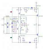
If I abandon the Thermaltraks and go with Nico's FET version, are these values OK? Retain 2SA/SC drivers, or use BC550/60? Leave or remove the driver emitter resistors?
I assume the drivers are run at lower current levels than for the BJT version. Am also assuming this version will be easier to stabilize for temp drift.
Sheldon
I assume the drivers are run at lower current levels than for the BJT version. Am also assuming this version will be easier to stabilize for temp drift.
Sheldon
Attachments
Hm... then I would like to understand how different is when input and general ground is separated and join ? (won't the input ground separated from amplifier ground sounds bad ?)
For 2-5 answer, its all incorporated because of TLP (remote) ? its like standby mode ? nice ^^
Input GND connection through 10 ohm resistor to main GND (antiparallel diodes serves to limit the resistor voltage drop to +/- 0,7 V and thus its max power dissipation) prevents interference currents to flow from source device because this 10 ohms resistance is around 10.000 times greater then direct GND connection from input RCA to main GND. This connection has to be done with separate wire from input RCA to main GND to equalize these two potentials to zero - same reference potential for input and output. Also in stereo amp left and right RCA's pins GND are connected together with short wire. This equalize potential between channels.
As you can see now the input GND is not separated from amp at all, there are simply two paths (exactly described above) made to prevent the hum & noise from interference currents.
TLP's when off, turns the output stage to high impedance state (Zout=Mohms) - BIGBT's are completely off, so you don't need an output relay.
... As long are they are not burned in short circuit !BIGBT's are completely off, so you don't need an output relay.
I performed some testing today before putting the channels to case assembly.
First I checked thermal stability of VAS bias current through 5 hours testing period. At cold start VAS bias current went from zero to 9,7 mA in 3 seconds period, than in next 1 minute it went to 10,8 mA and finally stabilized at 10,0 mA. When playing music loud main the heatsink becomes hot and within some pauses went back to 45°C, in between VAS bias current fluctuated between 9,5 mA and 10,5 mA, so difference was 10 mA +/- 0,5 mA, which I consider as a very good result. At the end VAS thermal influence with such simple compensation solution is ruled out from equation, so only Vbe multiplier has the standard role to prevent the output stage from thermal runaway.
Signal generator measurements with square waves shows no ringing at 100 kHz with speaker connected. Also I checked stability with Vout=120 Vpp at 100 kHz. There was smoke coming out from zobel resistor but on scope there was not a sign of any instability.
Than there was 2 MHz sine test which showed gain drop of only -0,8 dB and phase shift of some -15° between input/output signal.
After the signal generator testing there was a few hours of music listening and VAS bias current monitoring.
Output DC offset was within +/- 10 mV all the time, independent from thermal conditions present and this without any DC servo circuit.
Now, based on upper results, I think putting the amp together is quite realistic next step.
- Status
- This old topic is closed. If you want to reopen this topic, contact a moderator using the "Report Post" button.
- Home
- Amplifiers
- Solid State
- Simple Symetrical Amplifier