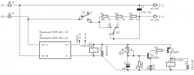
I wanted a softstart which would be simple and compact. Just an 1-2 second delay and the ability to use a small switch as on-off switch. Nothing more.
I also wanted proper separation of high-low voltage, wide tracks, no exposed 230V at the top of the board.
So I've drawn a small (6*9cm) pcb for it. Nothing special, 230V-16A relays powered by a small encapsulated smps. The big red areas are just a reminder of the distance to keep free.
Any mistake to correct ?
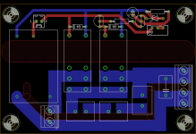
Attachments
Old'n'Cranky: two reasons mostly. AndrewT at some point mentioned that lower value resistors have thicker wire inside, making them more tolerant to big surges. And the second reason is that I can replace them with NTC if desired, which have to be in serie.
The higher surge rating for resistors under 50R can be seen in this datasheet for example: https://www.mouser.com/ds/2/303/res_tww_twm-1228653.pdf (10x vs 5x). In this serie, resistors above 50r aren't really wirewound anymore.
And the dissipation per resistor is the same in both case. Isn't the surge rating rated in W rather than A ?
ctrlx: yes, that's even simpler but then I'm loosing the ability to use a small switch to switch on the amp.
")
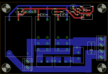
A slightly updated version. I added some pads to facilitate the use of thermistors. I'd use a pair of SL15 thermistor, rated at 30r and 4A continuous.
I also added a small header, allowing to take up to 12V/100mA if using the IRM-02-12; either before or after the switch.
I also added a small header, allowing to take up to 12V/100mA if using the IRM-02-12; either before or after the switch.
Attachments
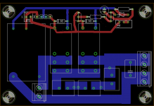
Yes, a single sided PCB is indeed possible and could be done at home.
However, I plan on using a professional dual sided anyway. The reasons are:
- it's the same price from Chinese small fabs for single or dual sided
- with a dual sided PCB, you get more solid plated through hole connections
- while a soldermask isn't a real insulation, it is still a small further protection
And since I've got two layers, I might as well use them to increase distance between tracks. In fact I might as well put all the low voltage tracks on top.
- Status
- This old topic is closed. If you want to reopen this topic, contact a moderator using the "Report Post" button.
- Home
- Amplifiers
- Power Supplies
- Simple softstart