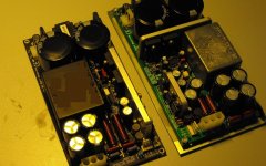
Thanks AP2, but if those arent separate output inductors lying horizontally at the output side of the board, then where are the output inductors?....and if its a LLC converter and doesnt have output inductors.....then what are those two inductors......they are power inductors...they are not ferrite bead type inductors.
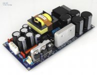
Also, when its doing 700W, whats the ripple current in the input electrolytics?.......and what are the mains harmonic currents?
Also, when its doing 700W, whats the ripple current in the input electrolytics?.......and what are the mains harmonic currents?
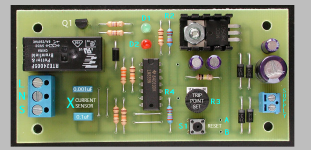
OVERCURRENT PROTECTION FOR IR2153 SMPS
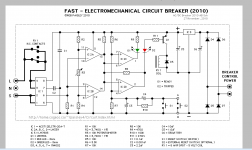
Circuit Breaker Features
Fast operation - Approximately 1/60th* of a second.
Adjustable trip current setting - 0.5 to 10 Amps.
No voltage or signal loss in the load circuit.
Power and Tripped indicator LED.
Low power consumption when reset.
Variable, Fixed and Asymetric trip current options are possible.
Attachments
Actually, you can build very nice and small SMPS using IR2153 ( without output voltage regulation ). But your schematic need little improvements ( you need to add snnubers, inpu NTC, and some kind of overcurrent limit.
You can find lots of stuff on net.
I am very happy with my IR2153 based smps.
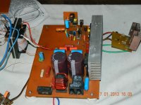
this diagram for smps Yamaha will not work. it is a false diagram. ir2135 will die after 1 second. be wary
- Status
- Not open for further replies.
- Home
- Amplifiers
- Power Supplies
- simple SMPS