OK, I checked the continuity on the switch. Checking between the two "top" tabs (these are the two tabs that are on the "on" position of the switch) they are always showing continuity between them whether the switch is off or on. Checking between the two "bottom" tabs (the ones on the "off" side of the switch and currently wired to my red and black wires in my pictures) I get continuity when the switch is off but when I switch it to on that connection breaks. Measuring between the either "side" of the switch (red to the transformer wire or black to the transformer wire) gives no continuity regardless of if the switch is on or off.
Anyway, I think you're probably right in that this switch is not a DPST but a SPDT. Am I right?
A single pole, double throw switch would have a terminal that connects to another terminal when the switch is one way, and it connects to a third terminal when the switch is the other way. That doesn't sound like what you've got.
Maybe you have a SPST switch with an indicator lamp in it or something. That might be the pair of terminals that always indicate continuity? I dunno. I'd be tempted to take the switch you've got, ignore the two "top" tabs (the ones always connected to each other) and just use the bottom two. Put the switch on the hot side of the power circuit, between the fuse and the PT. Wire the other leg of the PT's primary directly to the neutral terminal on the IEC receptacle.
Maybe you can see how I wired mine. My switch is a SPST with built in neon indicator. The third, unconnected terminal on my switch is for that. Ignore the fact that my ground connection isn't tied in for this photo. It was taken before the amp was complete.
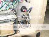
http://i69.photobucket.com/albums/i43/Ty_Bower/Simple SE/P1100519.jpg
Most helpful. I think I can make it work now. I'm running out the door to work now but will start switching wires when I get home (hopefully with a new RCA).
Ty, as an aside, I notice most of your wires are twisted in your picture; should I be doing that?
Also, with grounding does every jack, terminal, switch, etc need a separate wire to ground or can I wire them together and then just one one wire to ground? Also, if the RCA's are insulated, will they both need wires to ground? Both red and black binding posts need individual wires to ground?
You definitely want to twist the AC heater wiring (yellows and browns in your case). They can radiate 60 Hz noise which finds its way into the audio circuit. Twisting the leads does a remarkably effective job of canceling out that field. It is not critical that the twists be uniform, nor do they need to be any specific "twists per inch". Just twist them up by hand and they will do well.
You probably also want to twist anything else carrying AC, like the primary and HT secondary of the power transformer. These are a little more awkward. The primary side runs through switches and fuses that get in the way of neat twists. The HT side is center tapped, so you end up trying to twist three wires instead of two. Just do whatever you can. It doesn't hurt to twist the leads to the filter choke as well.
The wiring to and from the output transformers isn't as critical, but I like to twist it as well, mostly just to keep things a little neater. I tend to get enough piles of spaghetti underneath my amps as is. Here's some more underside photos of mine showing some of the twisted wiring.
http://i69.photobucket.com/albums/i43/Ty_Bower/Simple SE/P1100370.jpg
I agree with Tyler about the switch. Just forget about the top terminals and use the bottom two to switch the hot side on and off. Can you swap whatever markings say "on" and "off"?
For twisting 3 wires...I just leave the center tap out of the twist.
For twisting 3 wires...I just leave the center tap out of the twist.
Also, with grounding does every jack, terminal, switch, etc need a separate wire to ground or can I wire them together and then just one one wire to ground? Also, if the RCA's are insulated, will they both need wires to ground? Both red and black binding posts need individual wires to ground?
You're going a little overboard with the grounding scheme. It looks like your amp has the connectors and switches all mounted on a small metal plate, which is then attached to the side of your wood chassis. I would just put a ring terminal or something under one of the screws holding that plate to the chassis, and run a wire from that terminal back to ground. I can't see any value in running a separate ground lead to each individual switch. Likewise, your metal chassis top plate should be grounded for safety. I'm assuming the transformers are all mounted to the top plate.
You definitely do not want to run ground wires to the red and black binding posts. If you do, you'll short out the outputs of your amp. It probably won't damage anything, but it won't make any sound either. One of the binding posts should already be connected to audio ground through the Phoenix terminals on the circuit board, so there is nothing more here you need to do.
I like insulated RCA jacks. I think they can help avoid some ground loop (hum) issues. I wish I used them more often myself. You'll want to run four wires from the circuit board to the RCA jacks. One for each tip, and one for each ring. Land the wiring to the appropriate Phoenix terminals on the circuit board. The ring side is already connected to audio ground through the board. Per George's safety grounding instructions, you will want to run a chassis ground wire to only one of the RCA jacks. Tie it into the star point on the chassis top plate. This should be the only place where audio ground is connected to chassis ground.
You definitely do not want to run ground wires to the red and black binding posts. If you do, you'll short out the outputs of your amp. It probably won't damage anything, but it won't make any sound either. One of the binding posts should already be connected to audio ground through the Phoenix terminals on the circuit board, so there is nothing more here you need to do.
I was under the impression that if not using CFB I will need to ground the binding posts; is that not the case? I might use CFB later but I want to try it out in Triode mode before I do that. I think both my binding posts and RCA's are insulated from the chassis plate so I'm not sure if grounding the plate will also ground the connectors. It should take care of the switches though.
Anyway, I think I was able to save the RCA buy removing all the solder off the end with solder braid. I'm not in the process of twisting all my wires and getting everything re-done at the switch. With any luck I should have it all done tomorrow and I'll report back. Thanks for all the insight!
I was under the impression that if not using CFB I will need to ground the binding posts; is that not the case? I might use CFB later but I want to try it out in Triode mode before I do that. I think both my binding posts and RCA's are insulated from the chassis plate so I'm not sure if grounding the plate will also ground the connectors.
You should tie the black binding post to the Phoenix terminal on the circuit board. This will be T3-SEC:O1 and T2-SEC:O1, for the left and right channels respectively. This connects the binding post to audio ground. You must install the short jumper between O1 and O2, because you are not using CFB. I would avoid tying anything here directly to the chassis star ground, because it will likely cause a loop and result in hum.
Finally, you need to tie in the two leads from the OT's secondary. I think you are using an Edcor CXSE, so the leads should be yellow and white. I wish I could tell you which direction to connect the yellow and white leads from the OT. Fortunately, if you're not using CFB it doesn't really matter. Later, when you decide to try CFB, you'll have to figure out how your OT is phased. I'm going to guess the white wire needs to go to the red binding post, and the yellow wire needs to go to the black binding post. Maybe someone with an Edcor can chime in and tell us the correct answer. If not, you'll have to try it both ways. If one way results in a horrible shrieking noise, that's the wrong way. Otherwise, the way that results in quieter volume is the correct way.
Cathode feedback is independent of triode mode. Your first choice is either CFB, or no CFB. Your other choice is either triode mode, or ultra-linear (UL). Generally speaking, CFB tends to go well with UL mode.
It is good that your binding posts and RCA jacks are insulated. You should tie the metal plate to which they are mounted into the chassis star ground for safety. You do not want the binding posts and RCA jacks tied directly into the star ground. Doing so will likely cause a loop and result in hum. The black binding posts get tied into audio ground via T3-SEC:O1 and T2-SEC:O1, as described above. The red binding posts cannot be tied to ground, or the output channels are shorted and no sound will be produced. The RCA jacks are tied to audio ground through the circuit board (IN:2O and IN:4O).
You only want to connect the chassis ground to audio ground at one point. In your case, it will be through the wire you connect from the chassis star ground to the ring side of one of the RCA jacks.
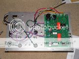
Here's a photo of the top side of the circuit board, so you can read the labels on the Phoenix connectors. You won't be able to see them with the board mounted in your chassis.
An externally hosted image should be here but it was not working when we last tested it.
http://s69.photobucket.com/albums/i43/Ty_Bower/Simple SE/P1100309.jpg
The yellow is the "positive" phase and the white is negative for the Edcors. Here is a picture of the wiring under my SSE. It's a little hard to tell because you can't see the colors of the binding posts, but you can see a black wire coming from the post that has the yellow wire on it. This is the extra ground on my amp, because I am using CFB. You can see that the black wires go back to the PCB, not to my star ground point which is on the far right near the choke.
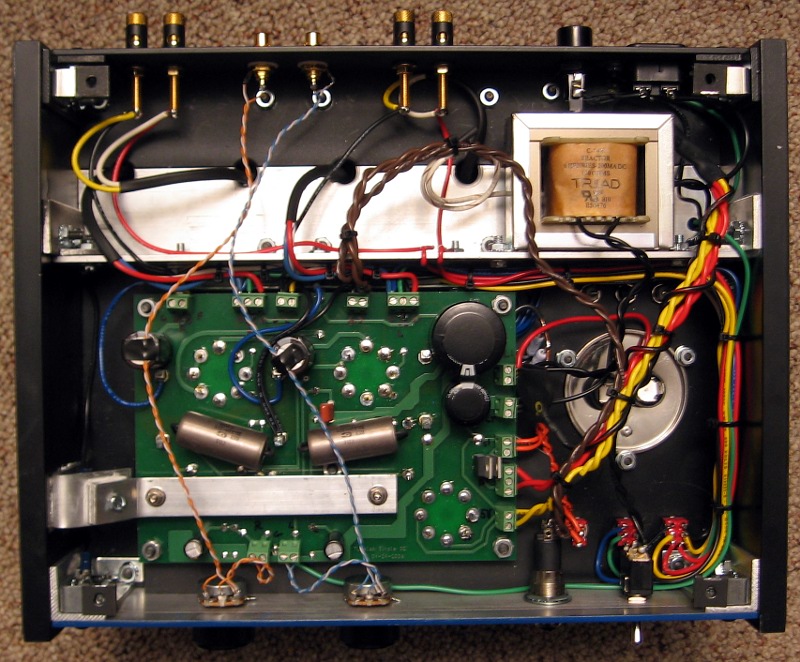
To reiterate what Tyler is saying, you only want ONE wire between your chassis and the audio portion of the amp. This includes the PCB, the OPTs, and the RCA jacks. My RCAs are fully insulated from the chassis and you can see a single green wire going from the ground point to the front of the PCB. This is my single ground.
To reiterate what Tyler is saying, you only want ONE wire between your chassis and the audio portion of the amp. This includes the PCB, the OPTs, and the RCA jacks. My RCAs are fully insulated from the chassis and you can see a single green wire going from the ground point to the front of the PCB. This is my single ground.
Russ just wondering when you wired your amp did you reverse the secondaries(8ohm to negative and common to positive) when wiring up cathode feedback? I was rereading the wiring diagrams trying to freshen up before I wire up my new amp and he mentioned some output transformers need to have this done? Did you do that with the edcors?
I'm so close! Grid resistor problem on 12AT7, fixed. Switch/power issue, fixed. Now I've got everything checked according to Ty's guide and everything checks out perfectly except for the HV on pins 4 and 6 of the rectifier... nothing there. 5V, no problem. 6.3V, no problem. No HV.
Just kidding... 😱 Forget to change the scale on my meter... HV, check! Now, that being said, it reads a little lower than Ty's guide. I'm only getting 380V at pin 4 and 6 on the rectifier. Is that an issue?
Just kidding... 😱 Forget to change the scale on my meter... HV, check! Now, that being said, it reads a little lower than Ty's guide. I'm only getting 380V at pin 4 and 6 on the rectifier. Is that an issue?
If you are within 5% or so you're definitely fine. Even 10% is OK. Could just be variation in line voltage.
Sheldon
Sheldon:
Thanks for the confirmation. I'm only getting 115V out of the wall so maybe that's it.
Now, another issue... I'm so close I can taste it now. Everything checks out, tubes light up, music plays... only through one side. I get VERY wait volume through one speaker, full volume through the other. The Edcor OPTs that I'm using say the yellow wire is the 8 ohm wire and the white is the common wire. I took that to mean that yellow goes to the red binding post and white to the black. I then tied a ground wire from the black binding post to the phoenix connectors on the PCB as recommended by TY. The thing that leaves me confused is that Russ has his ground wire coming off of his yellow wire and I have it coming off the white. Even more confusing is that one side works and the other doesn't. Any suggestions?
I did that because I had to invert the phase of the OPT in order to use CFB. It has to be swapped for the feedback to be negative. Otherwise it is positive and the amp gets louder with CFB on!
Well I've tried all the dumb-dumb stuff; switched tubes, switched wires, switched speakers, switched sides, switched preamp tubes, still stumped. Anyone have any suggestions on what to check next? The right channel is not totally dead, just VERY VERY quiet. The left channel sounds great though 🙂 !
Check you wiring and grounding for that right channel. I know you probably have but check again. Shoot another photo maybe someone can spot something with that channel. At least you have one working that is a good sign.
Sheldon:
Thanks for the confirmation. I'm only getting 115V out of the wall so maybe that's it.
Now, another issue... I'm so close I can taste it now. Everything checks out, tubes light up, music plays... only through one side. I get VERY wait volume through one speaker, full volume through the other. The Edcor OPTs that I'm using say the yellow wire is the 8 ohm wire and the white is the common wire. I took that to mean that yellow goes to the red binding post and white to the black. I then tied a ground wire from the black binding post to the phoenix connectors on the PCB as recommended by TY. The thing that leaves me confused is that Russ has his ground wire coming off of his yellow wire and I have it coming off the white. Even more confusing is that one side works and the other doesn't. Any suggestions?
I don't know if you are using any feedback now (UL, or Cathode), but I'd suggest setting the amp (or just the silent channel) up in triode mode (no feedback), then leave the output free floating - no earth connection to either side of the output. In other words, just the two output leads from that transformer, no other connection. Polarity won't matter for the test. See what you get.
Sheldon
I don't know if you are using any feedback now (UL, or Cathode), but I'd suggest setting the amp (or just the silent channel) up in triode mode (no feedback), then leave the output free floating - no earth connection to either side of the output. In other words, just the two output leads from that transformer, no other connection. Polarity won't matter for the test. See what you get.
That's a reasonable suggestion. You're not running cathode feedback, so the amp will still work with the secondary of the OPT floating. Just pull the lead from the binding post leading to the circuit board. The only remaining connection to the binding posts should be to the OPT.
Also make sure you didn't forget to install the jumpers on the circuit board. You need jumpers at T#-SEC (for no cathode feedback) and jumpers at T#-PRI (for triode mode). Confirm the Phoenix terminals are snug and the wires are secure. Look around for stray strands of wire that might have escaped and are touching somewhere they shouldn't.
Finally, I'm still a little suspicious of the RCA jacks, just based on their past history. Since the readings around the 12AT7 ohm'd out good, the RCA jacks are most likely fine. I still want to verify this. You don't need to unsolder anything. Just swap the wiring for the RCA jacks at the circuit board. Pull the wiring from the Phoenix terminals, and reverse the left side and right side inputs. Test the amp, and see if the problem moves to the other side.
- Status
- Not open for further replies.
- Home
- More Vendors...
- Tubelab
- Simple SE checkout for dummies