Stanley Beresford told me by email that the variable output puts out up to 1.35v and the direct out is more.
In your first post you talked about a 20 V transformer. If you have the standard gain-setting of the audiosector amp (680/22k = 33,35 times) and a 2 x 20 V transformer, the chipamp needs about 650 mV at the input for full output power. Anything above that will send it into clipping. And with that low capacitance you use, it will probably clip far below that, because the rails drop too much, too early.
How is your heatsinking? Too small heatsinks can also lead to distorted output, if the IC overheats and the protection system kicks in.
Thanks Pacificblue,
That's really helpful. Yes my transformer is 2x20v, chosen as my speakers are 6 Ohm nominal.
If the max input is 650Mv, that would explain everything. This amp is clipping like crazy with a normal direct input, and the level I found worked best was halfway around the headphone pot that has max output of 1.35v, so that works out perfectly. My 10k stepped attenuator seems not to be able to adequately attenuate the level to 650Mv, because of the 24 resistor combinations available, even the lowest level cannot avoid clipping fully. Does that make sense? Is my value wrong for this application?
What do you mean by "And with that low capacitance you use, it will probably clip far below that, because the rails drop too much, too early." As far as I am aware, the only capacitance I use is the 4x Panasonic 1000u smoothing caps.
I think my heatsinks are fine - they're as big as most I've seen in the gallery (about 100mm x 80mm x10, with fins). I use heatsink paste too, on insulated chips.
Many thanks again.
Lucas
Thanks Pacificblue,
That's really helpful. Yes my transformer is 2x20v, chosen as my speakers are 6 Ohm nominal.
If the max input is 650Mv, that would explain everything. This amp is clipping like crazy with a normal direct input, and the level I found worked best was halfway around the headphone pot that has max output of 1.35v, so that works out perfectly. My 10k stepped attenuator seems not to be able to adequately attenuate the level to 650Mv, because of the 24 resistor combinations available, even the lowest level cannot avoid clipping fully. Does that make sense? Is my value wrong for this application?
What do you mean by "And with that low capacitance you use, it will probably clip far below that, because the rails drop too much, too early." As far as I am aware, the only capacitance I use is the 4x Panasonic 1000u smoothing caps.
I think my heatsinks are fine - they're as big as most I've seen in the gallery (about 100mm x 80mm x10, with fins). I use heatsink paste too, on insulated chips.
Many thanks again.
Lucas
Yeah your heatsinks should be fine.. 1000uF seems low for this setup though. I'd have started it at 1500 and probably ended around 2200. In fact that's exactly what I did with a similar traffo and 6 ohm nom. speakers...
Hi Ray,
Sorry. My mistake. I just checked - they are 1500uF Panasonics, as supplied with Audiosector's GC kit.
Although there may be a subtle benefit to using 2200uF caps somewhere down the line, I'm guessing that's not the source of my clipping problem.
So, it seems I need to find the right resistor value at input to add to my 10k attenuator to suppress levels to below clipping. Does that sound about right? Is that the way to get the cleanest signal? This L Pad you talked about - how does that work?
Many thanks
Lucas
My 10k stepped attenuator seems not to be able to adequately attenuate the level to 650Mv, because of the 24 resistor combinations available, even the lowest level cannot avoid clipping fully. Does that make sense?
No. Are you sure, you connected it correctly?
In real life, the amplifier will clip below that point, because real power supplies sag under load. 650 mV is a theoretical value, with an ideal power supply that does not sag at all. Clipping could easily start 30 % below that, and the headphone pot will be a log type, which means the center position does not coincide with half the output voltage.
I think my heatsinks are fine - they're as big as most I've seen in the gallery (about 100mm x 80mm x10, with fins). I use heatsink paste too, on insulated chips.
On page 8 in the datasheet there is a table with recommended heatsink sizes for the unisolated package. You need to reduce the value you find in that table by 1 K/W, because you use the isolated package. Your heatsink would probably be enough for a single LM3875 at 25 °C. If you want to push it on a hot summer day, you will need a bigger heatsink or help yours with a fan.
Although there may be a subtle benefit to using 2200uF caps somewhere down the line, I'm guessing that's not the source of my clipping problem.
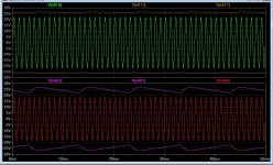
If the attenuator is not the reason for your clipping problem, don't bother increasing capacitance in so small steps. You need a big increase, like tenfold or so. Your amplifier with 1500 µF per rail will clip 15-20 % below the same one with 15000 µF per rail. Look at the difference in a simulation. The upper plot shows rails and output just below clipping with 15000 µF, the lower with 1500 µF.
Attachments
Hi Pacific,
the green trace show ~22Vpk for the signal with 15mF smoothing.
The red trace show ~18Vpk for the signal with 1500uF smoothing.
The 18Vpk signal is not obviously clipped on my screen resolution.
Was the input signal the same for both tests?
Why does the clipped peak (red) not follow the PSU ripple in the posted plot?
Both traces show the amplifier just short of clipping.
Clipping set in at 396 mV input signal with 1500 µF per rail, while with 15 mF per rail it started at 469 mV for a 6 Ohm resistive load. With 1500 µF the unclipped output swing is ~16,57 % lower than with 15 mF. That translates to ~28,71 % less undistorted output power, everything else being the same.
Clipping set in at 396 mV input signal with 1500 µF per rail, while with 15 mF per rail it started at 469 mV for a 6 Ohm resistive load. With 1500 µF the unclipped output swing is ~16,57 % lower than with 15 mF. That translates to ~28,71 % less undistorted output power, everything else being the same.
Hi Hi-fi helpers,
I am quite sure I have installed the attenuator correctly. I just checked the output of my DAC RCA, and it's 2v rms @ 0db when 16 bit signal is used it seems. So what is the usual procedure of inputting to a gainclone amp that has a theoretical maximum input of roughly one quarter that value? A valve buffer I've heard mention of? Resistors?
If the simple answer is resistors, what value range should I try and in what arrangement? If a "buffer" is better, what is it exactly please?
Please help. I'm really struggling here...
Many thanks
Lucas
The simple answer is resistors, which is pretty much the same as an attenuator.
You can put a resistor between the DAC and the attenuator. If you want the maximum signal at the attenuator input to 1/4 of the original, the resistor must have three times the attenuator's impedance. For your 10k attenuator that would be a 30k resistor, which leads to a total Rin of 40k.
In case your DAC needs a lower impedance, you can make an L-pad. Assume you want a total Rin of 10k, then the series resistor between DAC and attenuator would be 7k5. The parallel resistor from attenuator in to ground has to pull the attenuator's 10k down to 2k5, which leads to a value of ~3k3 for it.
a typical chipamp has a maximum output of ~20Vac.
The typical gain of a chipamp is 20 to 30times.
The maximum input signal is typically 600mVac to 1Vac.
You achieve sensible inputs to your power amplifier by using an attenuator between the source and the power amplifier.
An attenuator is a variable pair of resistors.
A fixed pair of resistors can be used to attenuate the signal before it reaches the Power amplifier.
You need somewhere between 10dB and 20dB of fixed attenuation before your power amplifier if you insist on omitting the conventional attenuator.
There is a big disadvantage to using a fixed low attenuation resistor chain. It presents a high source impedance to the following cable. Not good at preserving the frequency response of the system.
-12dB of attenuation would typically use a 10k resistor in line and 3k9 to ground when feeding Zin=22k.
The source resistance presented to the cable and amplifier input is ~ 2k8.
This is high and will be heard as a treble cut filter if the following capacitance load exceeds ~270pF.
Last edited:
I have decided to try out the Lightspeed Attenuator with my power amps (when they are built!). This is based on light dependant resistors (LDRs). If you believe the hype, the quality of the sound produced is unsurpassed by any other preamp available. The Lightspeed Attenuator sounds interesting to me, it's easy to build and cheap....so I thought I'd have a punt to see what all the fuss is about.
Anyway, matched sets of the LDRs are available on the diyAudio website here. Some of the proceeds goes to maintain this site. It also provides links to the main Lightspeed Attenuator discussion thread and a "How to build" website. So, might be worth a look.
Anyway, matched sets of the LDRs are available on the diyAudio website here. Some of the proceeds goes to maintain this site. It also provides links to the main Lightspeed Attenuator discussion thread and a "How to build" website. So, might be worth a look.
PJPro,
SKA audio sells a similar product in kit form for about $40 AU, including shipping. I used one for one of the amps that I built and have been very pleased. It's not really noticible at all, very transparent. The price is great, a lot less than a lightspeed attenuator.
PJN
SKA audio sells a similar product in kit form for about $40 AU, including shipping. I used one for one of the amps that I built and have been very pleased. It's not really noticible at all, very transparent. The price is great, a lot less than a lightspeed attenuator.
PJN
- Status
- This old topic is closed. If you want to reopen this topic, contact a moderator using the "Report Post" button.
- Home
- Amplifiers
- Chip Amps
- Simple pre-amp for gainclone help req'd.