Hi everyone,
I'm new at designing headphone amps, and I wanted to know if someone can help me to do a simple amplifier with a power between 500mW-1W to run 16-32 ohm headphones and maybe a small 8 ohm speaker. I've tried to apply the concepts of higher power amplifier designs such Randy Slone's designs and Bob Cordell's designs, but they have very poor output excursion. I wanted to do something similar to the TDA2822M (single supply and low voltage) in solid state, but with better THD characteristics.
Best regards,
Daniel Almeida
Attachments
Hi Daniel,
As soon as I get time I will start a project as shown here:
Zen headamp
It is a relatively complex discrete class A amp but its construction and setting up steps are very well detailed for beginners like us")
Cheers,
Jacques
As soon as I get time I will start a project as shown here:
Zen headamp
It is a relatively complex discrete class A amp but its construction and setting up steps are very well detailed for beginners like us
Cheers,
Jacques
You could always try something like this. Although I designed it for germanium it would transfer over to silicon with minimal change. Single supply, rechargeable battery or mains.
http://www.diyaudio.com/forums/head...rmanium-single-ended-class-headphone-amp.html
http://www.diyaudio.com/forums/head...rmanium-single-ended-class-headphone-amp.html
That's a typical case of the complexity - power - performance triangle. You could gain some linearity by going complementary in the output stage, while losing some output voltage swing on the negative side. You could also implement a CFP output stage in class A (which tends to be very linear, but don't you dare leaving A operation), which is a fair bit more power hungry but would tackle the main source of distortion. Otherwise you could go for a rail-rail output topology, but low-power, high-performance ones tend to be a fair bit more complex and not without their issues either. Finally there's the option of higher-order compensation instead of simple Miller compensation, at the expense of being more tricky to get right.
Last edited:
Hi everyone and thank you very much for your help,
I've made this amplifier with CFP class AB output stage, but the THD characteristics are very poor, I don't know if I can make changes in my design to improve THD characteristics, or if I should go for a more simple class A amplifier as Mooly and Jacques suggested. Can you send me the models for the transistors of your amplifier circuits? Please?
PS: I don't understand this class A amplifier topologies
They don't have negative feedback?
Best regards,
Daniel Almeida
Attachments
Quickly looked at your first file. Hugely complex for a headphone amp. Your distortion is probably a lot better than you think. I get it at nearer 0.005% on the file as it is. Try moving Vout to the load and increase the coupling and feedback caps to around 800000uf to take them out of the equation. DC shift and settling upsets the simulation.
Try a sqaurewave test at say 50kHz
Try a sqaurewave test at say 50kHz
You could always try something like this. Although I designed it for germanium it would transfer over to silicon with minimal change. Single supply, rechargeable battery or mains.
http://www.diyaudio.com/forums/head...rmanium-single-ended-class-headphone-amp.html
Are germanium transistors still available? I remember working with them way way back. I built a transformer coupled power booster for my car audio system (8-track
). This was before there were any bridge amps or switching supplies. It pretty much thumped. And it never even hiccuped. I thought it was pretty good for early 70s.I know they be hatin, but it was pretty good for super low tech designed and built by a 16 year old.
Watching the emitter current in the output transistors, you can see how things cross over to AB with an 8 ohm load and are firmly stuck there with 4 ohms. Like I said, CFP outside of class A is pretty nasty, as is the distortion profile that the circuit produces then. However, when firmly in class A at 32 ohms, distortion is limited by input stage / VAS! That's why e.g. the CK² III used such an output stage.
A class A output stage has nothing to do with using or not using global negative feedback. You can do that just fine, and in fact class A can be rather beneficial then because transistors run at higher emitter current are generally faster and (since the output stage generally is the slowest thing) require less compensation - another factor that reduces distortion.
Incidentally, practical headphone amps rarely need gains as high as 30 dB, certainly not if they're running off of 12 V single supply. (Maybe 26 dB with a wimpy MP3 player and 600 ohm cans. More typical values include 0-16 dB, depending on what you intend to be driving. With some loads you need to be shooting for under 5 µV of output noise.) I would also assume the input stage to be somewhat on the noisier side with this much degeneration (doesn't it translate to the input side times beta?). Oh, and the input biasing setup has lousy supply rejection. I would use a voltage divider, filter cap and resistor going from there.
Last edited:
PS:
The OP's circuit seems to handle a gain reduction to 5.7x (R3 = 4k7) just fine, whereupon simulated distortion at around 2 Vrms out and 32 ohms drops to ~0.0005% (and about 10 times that at 10 kHz). That's a pretty respectable result. Distortion at 8 and 4 ohms also fares much better in both numbers and spectrum, showing that a CFP output is best tamed by massive amounts of feedback. I'd say that if you do need higher closed-loop gains, adding another (differential) gain stage would be advantageous.
Incidentally, a CFP output in class A is so linear because it has massive local feedback. Each side essentially makes up a 2-transistor opamp circuit. Some people have actually used opamp buffers with driver transistors there (like this one), but things like that tend to be a pain to get stable.
Last edited:
You could certainly de-fancify your current sources a bit. 4 transistors each seems a bit excessive given the typically rather modest demands in audio amps.
Other than that, it's a rather usable topology (unsurprisingly, given it's basically a standard opamp topology). You'll still want to play with the input transistors / current / emitter degeneration (I think you have more slew rate than you realistically need) and read up on what Douglas Self writes on input stage and VAS distortion. Be warned that a Darlington VAS may introduce significant common-mode distortion though - if you do feel like adding a pre-VAS buffer, it better be a pnp, though that introduces a level shifting problem (some historic ICs would thus use both an npn and a pnp).
Incidentally, you can subject an amplifier like that to much of the same tests that Samuel Groner used in his opamp distortion evaluation. SPICE only models part of the factors responsible for input impedance distortion, but other than that simulation will already tell you a whole lot.
Hi sgrossklass and thank you for your help
What kind of current source is better for this design?
Feedback current source or diode/zener based current source?
Predrivers and output devices need a zobel network from base to collector, to prevent local oscillations, if parasitic capacitances appear?
Best regards,
Daniel
What kind of current source is better for this design?
Feedback current source or diode/zener based current source?
Predrivers and output devices need a zobel network from base to collector, to prevent local oscillations, if parasitic capacitances appear?
Best regards,
Daniel
Hi everyone,
I've made a few changes to my design to increase performance, what do you think?
PS:
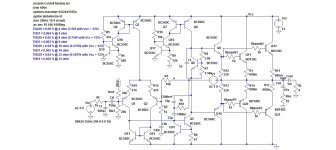
This is a low power class AB design for single supplies with TMC compensation scheme inteded to drive headphones and small 1W speakers.
Best regards,
Daniel
I've made a few changes to my design to increase performance, what do you think?
PS:
This is a low power class AB design for single supplies with TMC compensation scheme inteded to drive headphones and small 1W speakers.
Best regards,
Daniel
Attachments
Hi everyone,
I've made some changes to my headphones/small speaker single supply amplifier, using some technics of the higher power designs to improve THD characteristics
What do you think about that?
THD1 < 0.00004 % driving 16 or 32 ohm load at 0.37 W and 0.18 W of continuous sine wave power, respectively.
THD20 < 0.002 % under the same conditions.
Best regards,
Daniel
Attachments
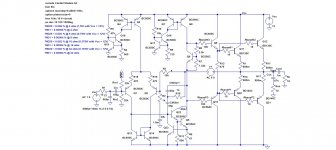
Still needs attention to input noise (too much degeneration) and supply rejection (input biasing still hasn't been fixed).
Also, BC550C isn't too great a VAS transistor, and may not be too happy as a driver either. When sticking with Bob Cordell's models, I'd suggest 2N5551/2N5401 for these parts. Not sure what would work well in the current sources, Early voltage is kinda low for BC550/560 even if their beta is high.
This one's no longer terribly rail/rail capable, obviously.
When reducing gain in a headphone application, swap R13 for a CCS to get rid of common-mode distortion.
Hi everyone,
Thank you for your help sgrossklass,
I've added an input decoupling network, the input noise density is 31.4 nV/rt(Hz), but I don't want to reduce degeneration, because if I do so I've to use higher compensation values to achieve the same stability margins, and so slew rate lowers and I have higher THD. How I can use a CSS instead of R13, do you know if there are any current source with less than 0.7V Vce sat?
I will try to replace later the VAS, drivers and CCS transistors for 2N5551/2N5401, but the advantage of BC550/560 pair is that they are low vce/low noise transistors and can produce lower THD characteristics, they have also an higher hfe. I will test the 2N pair but I'm happy with results produced by the BC pair in the simulation.
Best regards,
Daniel
Attachments
- Status
- This old topic is closed. If you want to reopen this topic, contact a moderator using the "Report Post" button.
- Home
- Amplifiers
- Headphone Systems
- Simple Headphone's Amp for beginner