Koinichiwa,
No, but you already have in place the TDA1545, which IMNSHO is a notably better chip than the TDA1543. If you like you can passive I/V conversion on the TDA1545 as well.
As a cynic (and based on what I have heard so far) I'd have to say that I rather doubt that, unless you go for a fullblown implementation of PCM1704 or PCM1738 or a suitable Cirrus Logic "High End" Chip, with all the relevant effort applied to Powersupplies, Analogue Stages etc....
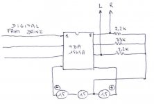
As for the TDA1545, just to put some cats among the pidgeons, I came across an interesting circuit from a French On-Line Mag, originated in the "dustcircle" of Pierre "Mr. MDI" Johannet for modding the Philips and Marantz Players using TDA1545 output Stages (Philips CD71X/72X and Marantz CD3X/4X) which I have attached.
You could use three "D-Cell" NIMH Batteries in this circuit, taking care to have a suitable "standby/float plus fast" charger which is simply disconnected when the Player is unmuted. Given the very low current Draw of this circuit you would likely get 2 - 3 Month battery life out of three non-rechargable high performance batteries, so completely omiting the charger and all may also be an option.
This would likely make for a VERY cost effective modification for the Philips and Marantz Players of this type, elimiating any active output Stage. Not shown in the Schematic are the Output Coupling Capacitors.
Oh, before I completely forgte, for adventerous souls, you could use a simple Silicon Diode (1N400X for example) string where each battery is replaced with three diodes as supply. Simply feed this diode string with a few 100mA current (from an LM317 connected as current source and a seperate mains supply) and things should work quite well to, you could even seek out adjustable references that can handle a few dozend mA and can supply 1.5 to 1.8V. In all cases I'd probably place one each BG NX-HiQ or Sanyo Os-Con on the Reference and Supply pin of the TDA1545 to ground.
Anyway, many options.
Sayonara
miguel2 said:
I understand that if the I2S signal is already oversampled, a simple TDA1543 design is out of the question.
No, but you already have in place the TDA1545, which IMNSHO is a notably better chip than the TDA1543. If you like you can passive I/V conversion on the TDA1545 as well.
miguel2 said:
I have to ask you if using a 192KHz chip would increase sound quality significantly.
As a cynic (and based on what I have heard so far) I'd have to say that I rather doubt that, unless you go for a fullblown implementation of PCM1704 or PCM1738 or a suitable Cirrus Logic "High End" Chip, with all the relevant effort applied to Powersupplies, Analogue Stages etc....
As for the TDA1545, just to put some cats among the pidgeons, I came across an interesting circuit from a French On-Line Mag, originated in the "dustcircle" of Pierre "Mr. MDI" Johannet for modding the Philips and Marantz Players using TDA1545 output Stages (Philips CD71X/72X and Marantz CD3X/4X) which I have attached.
You could use three "D-Cell" NIMH Batteries in this circuit, taking care to have a suitable "standby/float plus fast" charger which is simply disconnected when the Player is unmuted. Given the very low current Draw of this circuit you would likely get 2 - 3 Month battery life out of three non-rechargable high performance batteries, so completely omiting the charger and all may also be an option.
This would likely make for a VERY cost effective modification for the Philips and Marantz Players of this type, elimiating any active output Stage. Not shown in the Schematic are the Output Coupling Capacitors.
Oh, before I completely forgte, for adventerous souls, you could use a simple Silicon Diode (1N400X for example) string where each battery is replaced with three diodes as supply. Simply feed this diode string with a few 100mA current (from an LM317 connected as current source and a seperate mains supply) and things should work quite well to, you could even seek out adjustable references that can handle a few dozend mA and can supply 1.5 to 1.8V. In all cases I'd probably place one each BG NX-HiQ or Sanyo Os-Con on the Reference and Supply pin of the TDA1545 to ground.
Anyway, many options.
Sayonara
Attachments
Battery supply for TDA1543
Hi Kuei,
I think the resistors should be connected to ground as is the minus end of the string of batteries. And 33k should read 3k3.
A problem is the supply is 3x 1.5 = 4.5 V with alkaline or Zinc carbon batteries. Fedde would use four batteries giving 6V.")
Hi Kuei,
I think the resistors should be connected to ground as is the minus end of the string of batteries. And 33k should read 3k3.
A problem is the supply is 3x 1.5 = 4.5 V with alkaline or Zinc carbon batteries. Fedde would use four batteries giving 6V.
Battery supply for the TDA1543
Hi, Nice thing is it works and not worse than this supply:
http://www.diyaudio.com/forums/showthread.php?postid=181882#post181882
Helas, sounded not better either.......
Edit: oops my result is only for TDA1543. Forget my remark about the connections. TDA1545 is different in this respect. Kuei your picture is correct for TDA1545. I was concentrated on the TDA1543 as I don't like the 1545.
I was concentrated on the TDA1543 as I don't like the 1545.
You must be the only person that thinks so on this planet !
Jean-Paul, Weird feeling I can tell you........jean-paul said:
You must be the only person that thinks so on this planet !

? Goudreu triplets et al...
I searched back to find the post by Pete, I hope I am not quoting the wrong one (way too many people called Peter here<!>), but I am not sure what is being bypassed. I am guessing the analog supply pin of the DAC?
Peter Goudreu:
And btw, was the filter bypassed as in disabled, just on principle (real audiophiles don't need no stinkin' filters...), or was there something wrong with this part of the CD-94 design??
PM
The only thing I did to Marantz was bypassing digital filter, simplifying output stage to a single OPA627 per channel, removing DC reducing resistors network right at DACs output, changing all electrolytics to HFQ and Cerafines, adding local bypassing (Goudreu triplets).
I searched back to find the post by Pete, I hope I am not quoting the wrong one (way too many people called Peter here<!>), but I am not sure what is being bypassed. I am guessing the analog supply pin of the DAC?
Peter Goudreu:
A Panasonic HFQ 'lytic, 120uF/25V paralleled with an AVX 0612 270nF/25V Z5U chip cap paralleled with an AVX 0612 10nF/50V X7R chip cap. Note that these chip caps are 0612s, not 1206s. This yields a nearly perfectly resitive driving point Z out to about 90MHz or so. The residual inductance is on the order of 180pH which is swamped by the internal parasitics of the bypassed device's leadframe and bond wires. The 10nF should be mounted to the board first with the 270nF on top so that inductance at high frequencies is minimized.
And btw, was the filter bypassed as in disabled, just on principle (real audiophiles don't need no stinkin' filters...), or was there something wrong with this part of the CD-94 design??
PM
Another idea is to buy a used DAC and simply improve some parts.
I have a Sony SDP90 and for~100Euro (as you are from europe)
you can get one. Change some parts (20Euro) and you have a
digital preamp that plays in upper leagues.
I think this is easy for beginners as me and you.
I have a Sony SDP90 and for~100Euro (as you are from europe)
you can get one. Change some parts (20Euro) and you have a
digital preamp that plays in upper leagues.
I think this is easy for beginners as me and you.
Attachments
Re: ? Goudreu triplets et al...
I bypassed all 3 supply on TDA1541 in that way.
That part was fine (filter), but I wanted to try non-oversampling. I didn't remove the filter completely as I want digitalt output as well.
PMiczek said:
I searched back to find the post by Pete, I hope I am not quoting the wrong one (way too many people called Peter here<!>), but I am not sure what is being bypassed. I am guessing the analog supply pin of the DAC?
And btw, was the filter bypassed as in disabled, just on principle (real audiophiles don't need no stinkin' filters...), or was there something wrong with this part of the CD-94 design??
PM
I bypassed all 3 supply on TDA1541 in that way.
That part was fine (filter), but I wanted to try non-oversampling. I didn't remove the filter completely as I want digitalt output as well.
Wombat,
SDP90 I am not familiar with, and do not know what is inside.
I _have_ heard the sdp-E800, quite impressive for movies and surround sound, but pretty much ruined 2-channel audio for my taste, just like the HT setup I own, unless I turn off all the features and use it in stereo mode. Did not think you could do much with the E-800, but never looked closely or asked anyone. Checking today, E800s sell for about $100 on ebay.
Peter,
Q: why bypass all supply pins in such an elaborate manner? Was this really necessary, or one of those "preventive" measures?
Btw, Am relieved to hear you did not jettison your filters completely, I am rather fond of mine.
PM
(I think we have departed from the "simple" part of the original thread now...)
PMiczek said:
Q: why bypass all supply pins in such an elaborate manner? Was this really necessary, or one of those "preventive" measures?
I didn't compare ea. supply before and after bypass and preffered do them all at once. So we could call it preventive measures
and the answer is...
Was the consensus in favor of making modifications to what is already a pretty good CDP w/o replacing or adding a DAC chip, or was it in favor of adding a board with a TDA1543 or similar simple DAC? (I realize there is no one RIGHT answer here, but I am curious if there is agreement among people who have done both, in this one particular case).
Was the consensus in favor of making modifications to what is already a pretty good CDP w/o replacing or adding a DAC chip, or was it in favor of adding a board with a TDA1543 or similar simple DAC? (I realize there is no one RIGHT answer here, but I am curious if there is agreement among people who have done both, in this one particular case).
Hi Kuei
This weekend I opened my marantz cd48 to do the modifications you mentioned. But instead of a TDA1545 I found a surface mount 16 pin TDA1549. With 16 tiny tiny legs I really dont' want to mess with it. But then I though I could get the I2S signal from it by soldering some wires to the respective (sooo tiny) legs, and then use an external dac chip. Would this work, I mean, would it be ok to connect the I2S signals to 2 dac chips? This way I would keep the cdp working in its original state and would have an external dac chip to play with passive conversion, like the circuit you have mentioned.
Miguel
Koinichiwa,
Seems you are somewhat unlucky.
Seems Marantz "upgraded" the CD - 4X after the version i encountered to be based on the Philips CD-75X series, instead of the (in some ways as "DIY Upgrade Platform" superior CD71X/72X).
The TDA1549 is internally very similar to the TDA1545 in some ways, but it replaces the passive divider with a "Bitstream/Delta-Sigma" modulator and places the Op-Amp's on board of the chip.
For best sound from this take the output directly of the chip outputs (pin4/7) and take care to improve the quality of Cext (pin 8) and of the output coupling Cap's.
Sure. The I2S input pins on the TDA1549 are:
Data - 16
LCRCK/WS - 1
Bitclock - 2
The data of course is still 4 * Oversampling.
Sayonara
miguel2 said:
This weekend I opened my marantz cd48 to do the modifications you mentioned. But instead of a TDA1545 I found a surface mount 16 pin TDA1549.
Seems you are somewhat unlucky.
Seems Marantz "upgraded" the CD - 4X after the version i encountered to be based on the Philips CD-75X series, instead of the (in some ways as "DIY Upgrade Platform" superior CD71X/72X).
The TDA1549 is internally very similar to the TDA1545 in some ways, but it replaces the passive divider with a "Bitstream/Delta-Sigma" modulator and places the Op-Amp's on board of the chip.
For best sound from this take the output directly of the chip outputs (pin4/7) and take care to improve the quality of Cext (pin 8) and of the output coupling Cap's.
miguel2 said:
Would this work, I mean, would it be ok to connect the I2S signals to 2 dac chips? This way I would keep the cdp working in its original state and would have an external dac chip to play with passive conversion, like the circuit you have mentioned.
Sure. The I2S input pins on the TDA1549 are:
Data - 16
LCRCK/WS - 1
Bitclock - 2
The data of course is still 4 * Oversampling.
Sayonara
Miguel2,
With a trick you can even bypass the TDA1549's internal opamps.
Replace the external filter capacitors (Cext1 and Cext2, see datasheet) with shortcuts.
Now you have a current output and can use your favourite I/V opamp or discrete circuit by feeding the TDA1549 outputs again into the -input and connecting the Vref to the +input of your new I/V stage (I always liked LM6172 at that location).
Compared to the TDA1545A and feeding it with the same 4*fs signal from the SAA737X servo/decoder, it sounds less digital IMHO.
For starters I would get the maximum performance from your Marantz CD48 player first; feed the DAC from three individual supplies, use direct voltage output from DAC or bypass internal opamp and add "better" output stage, and, assuming this player has 8.X MHz clock like the Philips CD75X series, replace it with a Tent clock or Kwak clock, but also connect it directly to the BCK input of the TDA1549 as well.
KYW,
Does the Philips 72X series have 1*fs I2S signals ? How's the space inside these players, like the newer 75X series ?
Regards,
Hi Kuei and Rudolf,
I never worked with SMD chips before and I dont want to ruin this cdp. So for now I am buying a TDA1543 and connect it to the I2S signals taken from the TDA1549 pins. I want to hear this first before atempting something more complicated with those small pins. I saw Peter Daniels circuit on this cheap, with 1K on the output and 47k to ground and I will try that. I will use batteries for power the chip, as Kuei suggested. As I am not buying expensive caps for now, I was thinking in using back to back regular elecytrolytics (4.7uF), but dont know if this back to back arrangement has any advantage.
Miguel
Konichiwa,
Did you try this actually?
I would expect this not to work, as with Cext shorted the inverting input is still a virtual ground, sinking all the current from the DAC and delivering non externally. But I'm happy to stand corrected and would like to have a way to circumvent these sections in the various Philips DAC's...
No.
The 71X/72X is basically empty, apart from X-Port and mains TX.
If you trace the pin's and their PCB traces you can probably find a point where there is a jumper wire or a resistor to slow down the edge of the signal. Solder to there, it's much easier.... ;-)
Use miniature PTFE Coax cable, ground screens at the DAC only and use a piece of copper foil (insulated) or silverfoil to make a low inductance ground return from DAC to Player PCB.
Actually, for the TDA1543 I would recommend 6 or 7pcs "D" Cell rechargables with a suitably scaled I/V resistor (I hear 1K5 should work well). Then put a 2K2 adjustable at the Ref pin and adjust the resistor for lowest distortion (preferably using a 0dbfs test cd and and a 'scope) with the batteries near "empty" (1V per battery).
To simulate empty batteries when having full batteries use only 4 or 5 pcs "D" Cells to set the reference Voltage, then connect the other cells to go.
The TDA1543 draws a lot more current than the TDA1545, so powring it from non-recharables will drain your batteries and pockets fast.
Not in this case. Use one Cap, plus towards the DAC.
Sayonara
rbroer said:With a trick you can even bypass the TDA1549's internal opamps.
Replace the external filter capacitors (Cext1 and Cext2, see datasheet) with shortcuts.
Now you have a current output and can use your favourite I/V opamp or discrete circuit by feeding the TDA1549 outputs again into the -input and connecting the Vref to the +input of your new I/V stage (I always liked LM6172 at that location).
Did you try this actually?
I would expect this not to work, as with Cext shorted the inverting input is still a virtual ground, sinking all the current from the DAC and delivering non externally. But I'm happy to stand corrected and would like to have a way to circumvent these sections in the various Philips DAC's...
rbroer said:Does the Philips 72X series have 1*fs I2S signals ?
No.
rbroer said:
How's the space inside these players, like the newer 75X series ?
The 71X/72X is basically empty, apart from X-Port and mains TX.
miguel2 said:
I never worked with SMD chips before and I dont want to ruin this cdp. So for now I am buying a TDA1543 and connect it to the I2S signals taken from the TDA1549 pins.
If you trace the pin's and their PCB traces you can probably find a point where there is a jumper wire or a resistor to slow down the edge of the signal. Solder to there, it's much easier.... ;-)
Use miniature PTFE Coax cable, ground screens at the DAC only and use a piece of copper foil (insulated) or silverfoil to make a low inductance ground return from DAC to Player PCB.
miguel2 said:
I saw Peter Daniels circuit on this cheap, with 1K on the output and 47k to ground and I will try that. I will use batteries for power the chip, as Kuei suggested.
Actually, for the TDA1543 I would recommend 6 or 7pcs "D" Cell rechargables with a suitably scaled I/V resistor (I hear 1K5 should work well). Then put a 2K2 adjustable at the Ref pin and adjust the resistor for lowest distortion (preferably using a 0dbfs test cd and and a 'scope) with the batteries near "empty" (1V per battery).
To simulate empty batteries when having full batteries use only 4 or 5 pcs "D" Cells to set the reference Voltage, then connect the other cells to go.
The TDA1543 draws a lot more current than the TDA1545, so powring it from non-recharables will drain your batteries and pockets fast.
miguel2 said:
As I am not buying expensive caps for now, I was thinking in using back to back regular elecytrolytics (4.7uF), but dont know if this back to back arrangement has any advantage.
Not in this case. Use one Cap, plus towards the DAC.
Sayonara
Yup.Originally posted by rbroer
With a trick you can even bypass the TDA1549's internal opamps.
Replace the external filter capacitors (Cext1 and Cext2, see datasheet) with shortcuts.
Now you have a current output and can use your favourite I/V opamp or discrete circuit by feeding the TDA1549 outputs again into the -input and connecting the Vref to the +input of your new I/V stage (I always liked LM6172 at that location).
Did you try this actually?
I would expect this not to work, as with Cext shorted the inverting input is still a virtual ground, sinking all the current from the DAC and delivering non externally. But I'm happy to stand corrected and would like to have a way to circumvent these sections in the various Philips DAC's...
The "virtual ground" or in fact "virtual Vref" is just an abstract result of the feedback loop; there's no way the opamp input stage sinks or sources current. One only looses some really minor bias current (pA ~ nA) for the input stages, but the current can only flow through Riv (made 0 ohms in this case)
A few years ago when still using opamps, I used the LM6172 which gave a nice improvement over the DAC's internal opamps.
Current Output DACs
Hi,
I found this old post on the Audio Asylum:
http://db.audioasylum.com/cgi/m.pl?forum=tweaks&n=56612&highlight=current+voltage+converter&session=
With The TDA1543 I found the OPA604 performs very well. Connection is as in the datasheet of the TDA1543. The resistor from Vref to ground is 3k3 as used by Philips in there players (CD380 etc.). Offset at the output is not too high but not zero.
I also tried the "looped cascode" by Wildmonkeysects and the one transistor scheme by Thijs Schrama but I was not impressed.
I feel if the first pole of the analog lowpass filter is in the IV-converter [cap across the feedbackresistor] the demands on the opamp are not that high i.e no need for ultrahighspeed opamp like AD817, LM6172.
I also tried the "looped cascode" by Wildmonkeysects and the one transistor by Thijs Schrama but I was not impressed.
Hi Elso,
Just incase anybody cares: the one-transistor I/V stage was just a very very simple circuit to increase the dynamics of my TDA1541A DAC compaired to a passive resistor I/V. Clearly Jocko's simple I/V would be the obvious next step as it would be a clear improvement if only from an enginering point of view.
Regards,
Thijs
- Status
- This old topic is closed. If you want to reopen this topic, contact a moderator using the "Report Post" button.
- Home
- Source & Line
- Digital Line Level
- Simple, good quality DAC