A 3F capacitor is possible but usually only available in very low voltages (2-4V DC), for microprocessor memory storage. There are some higher voltage rated types, up to 16V or more but that is becoming very expensive. Are you sure that the "F" you read on the capacitor really means "Farad"? In my experience it does not. I suspect it is used as a decimal indicator, like 3F3 instead of 3.3. So, perhaps 3F really means 3µF.
I imagine that a capacitance meter might be too expensive for checking what you have but the popular parts testers and kits based on ATMEGA328 chips are cheap and most will measure up to 1000µF or more with reasonable accuracy.
I imagine that a capacitance meter might be too expensive for checking what you have but the popular parts testers and kits based on ATMEGA328 chips are cheap and most will measure up to 1000µF or more with reasonable accuracy.
It's a step. Go for it.

Mr. Nelson Pass! OMG thank you sir I watched your interview by Steve Gutenberg, fascinating... Thank you so much for the encouragement.
Basic Hifi_ that course looks a respectable one.
My own proposal for a syllabus would include, probably in this order:
Kirchoff's current law (really simple, really)
Network analysis using the above (this should really follow on directly, but I've not looked into courses recently to check)
- reason is that this will introduce how simulation is done too, and help with understanding simulations.
Even basic maths regarding a simple resistor network in matrix form will help to understand this. Extending to non-linear thingys like diodes and transistors is more complicated as these have to be linearised and solved iteratively.
Diodes, BJT's and MOSFETs (not all at once. Diodes are first and once you get a grasp of how those work BJT's are a little easier. MOSFETs also have their unique differences.
Then I'd go to op-amps rather than the other way round.
Much of the designs on here are discrete - that offers great flexibility (to get things wrong as well as right).
Opamps last, first the idealised stuff (inverting/ non-inverting/differential/maths operations) but also looking at specs and real performance from actual devices.
For audio you could also read Self or Cordell's books.
Maybe you can check your course syllabus in detail compared with my list above.
I don't need to know - this is just for your benefit.
If that were my design I would choose to use a 50W power resistor and put that on an additional heatsink.
Many computer grade capacitors have equivalent series resistance and inductance (ESR, ESL) specified and are low which would make additional parallel components unnecessary.
But the circuit obviously works as shown and would probably work with many other FETs too.
Running at 9V pushes the FET into its low voltage "triode" region and if you need that to be reasonably linear, a higher current (low on resistance) FET may be better and at low voltages there are many high current/low on resistance devices to choose.
The circuit is not so different from your original concept (using a load resistor ) and it could work with a bipolar too, but at lower voltages quasi-saturation will give a non-linear response too so that means it competes with a FET for best performance! (and the BJT will need a much lower bias resistor closer to your 270 ohms to provide base current)
Many computer grade capacitors have equivalent series resistance and inductance (ESR, ESL) specified and are low which would make additional parallel components unnecessary.
But the circuit obviously works as shown and would probably work with many other FETs too.
Running at 9V pushes the FET into its low voltage "triode" region and if you need that to be reasonably linear, a higher current (low on resistance) FET may be better and at low voltages there are many high current/low on resistance devices to choose.
The circuit is not so different from your original concept (using a load resistor
) and it could work with a bipolar too, but at lower voltages quasi-saturation will give a non-linear response too so that means it competes with a FET for best performance! (and the BJT will need a much lower bias resistor closer to your 270 ohms to provide base current)My background in in computers - with postgraduate qualifications and many years of experience. When it comes to electronics, though, I am still at the beginning. Part of the reason, though, is the way it is presented. I will need to learn some stuff, maybe a forum is the best thing. In the meantime I am watching videos on electricity (not on single transistor amps from CFL bulbs) and it is becoming clearer.
I do need to ask where I can get a good look at types of transistors and what their characteristics are, and which are suitable for low power amplifiers.
50W power resistor? As the collector resistor, this one is not too expensive:
https://www.amazon.com/TiToeKi-Resistor-Aluminum-Wirewound-Resistors/dp/B07SPC8CKK/ref=sr_1_20?dchild=1&keywords=1+ohm+50+watt+resistor&qid=1635328727&qsid=136-4036312-0777258&sr=8-20&sres=B08545DNNR%2CB07HC8CH2N%2CB08QRCZFWR%2CB008IDAD76%2CB098QKYXQC%2CB07QY6365F%2CB07XHG9DVJ%2CB077BS9YHP%2CB07QX4LQTR%2CB007Z7KMDG%2CB08FHPJ5G8%2CB072BL2VX1%2CB08DQRV8TT%2CB07DCBRKQX%2CB07TP4GYN8%2CB07SPC8CKK
Running at 9V pushes the FET into its low voltage "triode" region and if you need that to be reasonably linear, a higher current (low on resistance) FET may be better and at low voltages there are many high current/low on resistance devices to choose.
I do need to ask where I can get a good look at types of transistors and what their characteristics are, and which are suitable for low power amplifiers.
50W power resistor? As the collector resistor, this one is not too expensive:
https://www.amazon.com/TiToeKi-Resistor-Aluminum-Wirewound-Resistors/dp/B07SPC8CKK/ref=sr_1_20?dchild=1&keywords=1+ohm+50+watt+resistor&qid=1635328727&qsid=136-4036312-0777258&sr=8-20&sres=B08545DNNR%2CB07HC8CH2N%2CB08QRCZFWR%2CB008IDAD76%2CB098QKYXQC%2CB07QY6365F%2CB07XHG9DVJ%2CB077BS9YHP%2CB07QX4LQTR%2CB007Z7KMDG%2CB08FHPJ5G8%2CB072BL2VX1%2CB08DQRV8TT%2CB07DCBRKQX%2CB07TP4GYN8%2CB07SPC8CKK
Last edited:
You need lower dissipation if planning on running Class A. Use basic TO247 like 2SC5200N for NPN.
MOSFETs are also good for speaker output stage. Try IRFP240 etc.
For simple amps…
Here is one of the simplest amplifiers by Nelson Pass. I have always wanted to try this one:

A mosfet and lightbulb. Doesn’t get much simpler and you can use solderless P2P connections for this one I am sure. The above needs a depletion mode FET though. Probably LU1014D would work with a lower voltage like 19v laptop brick.
De-Lite Amplifier
MOSFETs are also good for speaker output stage. Try IRFP240 etc.
For simple amps…
Here is one of the simplest amplifiers by Nelson Pass. I have always wanted to try this one:
A mosfet and lightbulb. Doesn’t get much simpler and you can use solderless P2P connections for this one I am sure. The above needs a depletion mode FET though. Probably LU1014D would work with a lower voltage like 19v laptop brick.
De-Lite Amplifier
Last edited:
I checked the Georgia Tech course.
1) it is not free!!!!
2) at the same time looks like too little, too fast, too much content for a couple classes, just skimps on basics, etc.
3) sincerely, to me it looks like a useless course, only interested in selling a Certificate you can add to your LinkedIn profile which looks like you accomplished something and not much more.
They say so in so many words!!!
Ever heard the phrase Diploma Mills?
Diploma mills in the United States - Wikipedia
This one claims an association with respectable Georgia tech and in fact Instructors might be regular teachers there, even get a wink from somebody at the University (a friend/colleague?) but the actual Diploma is issued by Cursera, not the University.
That besides the fact of being way incomplete.
"Basics>Op Amps>diodes>diploma" in that order?
Watching videos online?
Tell me it´s a joke.
I always suggest getting at a local Library a PHYSICS book, the older the better, pre-50´s even better, the Electricity and Magnetism section, to learn the basic CONCEPTS on what is a resistor, capacitor, volt, ampere, ohm, battery, power, impedance, conductor, insulator, etc.
1) it is not free!!!!
2) at the same time looks like too little, too fast, too much content for a couple classes, just skimps on basics, etc.
3) sincerely, to me it looks like a useless course, only interested in selling a Certificate you can add to your LinkedIn profile which looks like you accomplished something and not much more.
They say so in so many words!!!
Shareable on
You can share your Course Certificates in the Certifications section of your LinkedIn profile, on printed resumes, CVs, or other documents.

What will I get if I purchase the Certificate?
When you purchase a Certificate you get access to all course materials, including graded assignments. Upon completing the course, your electronic Certificate will be added to your Accomplishments page - from there, you can print your Certificate or add it to your LinkedIn profile.
Ever heard the phrase Diploma Mills?
Diploma mills in the United States - Wikipedia
This one claims an association with respectable Georgia tech and in fact Instructors might be regular teachers there, even get a wink from somebody at the University (a friend/colleague?) but the actual Diploma is issued by Cursera, not the University.
That besides the fact of being way incomplete.
"Basics>Op Amps>diodes>diploma" in that order?
Watching videos online?
Tell me it´s a joke.
I always suggest getting at a local Library a PHYSICS book, the older the better, pre-50´s even better, the Electricity and Magnetism section, to learn the basic CONCEPTS on what is a resistor, capacitor, volt, ampere, ohm, battery, power, impedance, conductor, insulator, etc.
That resistor you found is the sort I'd choose, but reminder that it needs a heatsink depending on the actual power it will be dissipating.
The value of the resistance depends on the volts/amps you want out. That, in turn, depends on the power out and the load resistance (loudspeaker being the ultimate load).
A simple amp could, maybe, provide a few watts. If you want to runthe design at 9V the optimum you can do would be 3V into 3ohms, needs 1A peak, gives 1.5W rms out.
THerefore the collector/drain electrode has to be biased to 3V while having a reasonably linear capability to swing to a low voltage (Vce(sat) for a BJT or limited by Rds(on) for FET; but that may well need a significant gate voltage drive (depending on the FET characteristics)).
In short the resistor needs to drop 9-3=6V and pass 2A (making the transistor work at 2A as well) so should be a 3 ohm device with 12 W dissipation. So a 25W resistor would be adequate for this example.
As well, the transistor has to pass up to 4A peak and go to zero, a large signal swing, with potential for distortion figures of 10% or more without decent feedback.
If you don't follow the reasoning behind the figures, you really do need to learn some basics and I'd concur with JMFahey - I missed the point that the course was not actually a Georgia Tech one nor seems to be accredited. Many older books will cover the basics although quasi -saturation dates from perhaps the late 70's when epitaxial base technology became the dominant method of manufacturing (existed before then but it takes techy books a few years to catch up). Power MOSFETs too only appeared in the 80's so looking up IR's (now part of Infineon) early Hexfet info may be useful.
As a simple evaluation what is the efficiency of the circuit if the collector (assuming a BJT) load resistor was 3 ohms and the speaker impedance was also 3?
You should be able to work out the (collector) load resistance for peak efficiency? (as a ratio to the load).
(Clue: you just have to assume that whatever transistor you use is able to be set to the volts/amps needed, however that might be achieved in practice i.e. don't worry about the device as such. Just see if you can use Ohm's law and power equations. And the peak efficiency is where the (collector) load resistor is not the same as the load!)
Last edited:
I experimented with a similar thing when I was a kid - in the late 60's. Mine didnt have the 3F cap and I remember the speaker cone would be sucked in a bit when on. I used a big output transistor from a car radio, with the heatsink it was originally mounted to.
......
Unsure if the autotransformers are unobtanium these days. Class A from the 60's! Too bad I never pursued it - never thought it'd be a thing 50 years hence! Who'd want one of these lame things when you could buy a "Lil Tiger" kit from SWTP and get 20W so easy?
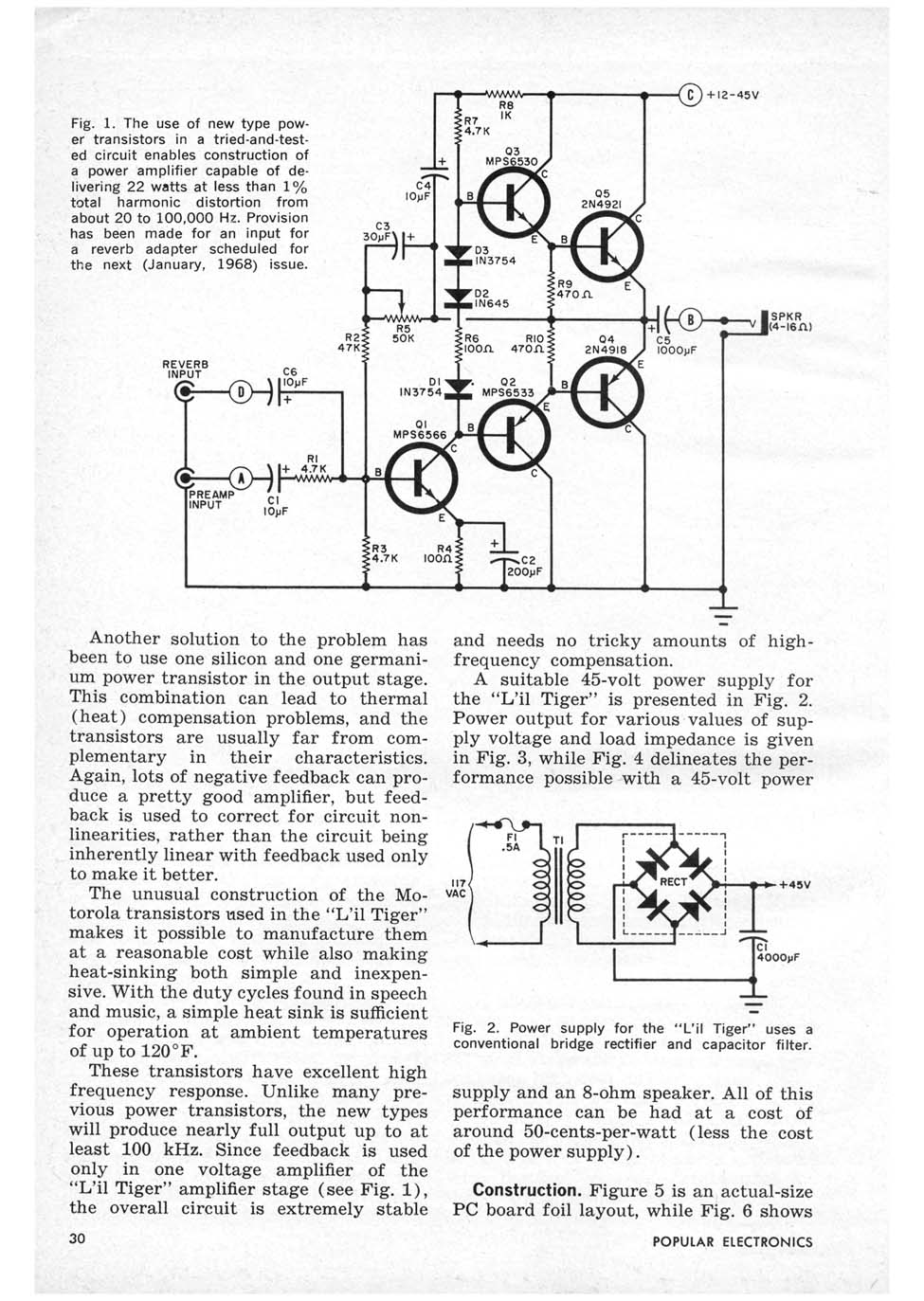
How did it sound? And also, out of curiosity, is the "Lil Tiger"depicted down the page here?
It's ancient!
https://www.wass.net/othermanuals/SWTPC.pdf

There is a lot of reference to 'constant current source' in these simple class A circuits, sometimes provided with a resistor.
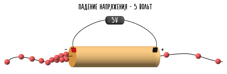
How can a passive component like a resistor can produce a current?
And here it is:
Constant Current Source: Transistor Active Source >> Electronics Notes
Voltage much higher means that the heat dissipated by this resistor will be high.
How can a passive component like a resistor can produce a current?
And here it is:
The simplest form of constant current circuit uses a single electronic component: a resistor. If the voltage of the source voltage is much higher than the voltage where the current is required, then the output current will be almost independent of the load.
Constant Current Source: Transistor Active Source >> Electronics Notes
Voltage much higher means that the heat dissipated by this resistor will be high.
Last edited:


I do not believe this is a legit question.There is a lot of reference to 'constant current source' in these simple class A circuits, sometimes provided with a resistor.
How can a passive component like a resistor can produce a current?
You are TROLLING us, just pulling the string more and more to find where it breaks.
Having lots of (sick) fun meanwhile.
Scientifically described in:
Attention Seeking Behavior in Adults: Causes, Other Symptoms, More
Specially :
pretending to be unable to do something so someone will teach, help, or watch the attempt to do it
Fits like a glove.
How did it sound? And also, out of curiosity, is the "Lil Tiger"depicted down the page here?
It's ancient!
https://www.wass.net/othermanuals/SWTPC.pdf
Ha! I built a couple of those kits back then, used them in my little bedroom recording studio. They did the job and were reliable, that's mostly what I cared about back then.

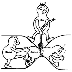
Great diagrams for illustrating resistance, thanks.
As for trolling, that would mean I already know the answers to the questions I ask before I ask them? That amounts to a heck of a lot of knowledge already, thanks for the compliment.
The reality is I have learned much and it has been nice to get all the help.
As for trolling, that would mean I already know the answers to the questions I ask before I ask them? That amounts to a heck of a lot of knowledge already, thanks for the compliment.
The reality is I have learned much and it has been nice to get all the help.
- Home
- Amplifiers
- Solid State
- Simple Class A Amplifier Project