I don't use simulators, just build, test, measure and listen. I still don't get it: why carbon is better than metal? If you really want to get rid of HF noise, you put a capacitor between inverting and non-inverting inputs of the chip and/or a low pas fillter at the input. Those resistors have nothing to do with efficiency.
The all band performance of metal film resistors is better for loads, and its more efficient at this task.
Remember that the project is also about symmetry of a chipamp on bass with a vacuum tube amp on mids and treble.
Yes, thank you for mentioning the cap. The physical model has a 100pF ceramic cap as a load across the pins of the RCA jack. The capacitive load is pin-to-pin with the input cap at the RCA jack (divides by zero). Anyway, there is a load on both sides of the input filter cap. Its 100pF on the jack side and 10k metal film on the subwoofer amplifier and the input filter cap is in-between these two loads.
Inductance took a hike.
")
Yes. That 100pF value is a bit weak/conservative; however, the exact nature of the source device is known to only one person.
Even more interesting than these technologies is the vacuum tube based active system that the thread owner is creating to blend these little subwoofer amplifiers with his vacuum tube amplifier.
Once the vacuum tube amplifier is set free from bass duty, it may be capable of cleaner and more powerful output. I'd love to hear about this.
Daniel / Ratza
Let's not get into a "my chip is bigger than yours" debate over this. These types of discussions also go on "ad infinitum" in the tube/valve forums also.
I DO NOT use ANY modeling beyond a few programs that automate F3 points and plot some more complex load lines for my valve designs.
I instead rely upon the basic math models and mfr. data for anything I build.
There is however some subtle differences in resistor and capacitor properties which are "accepted" norms in the tube world. These I am sure have actual hard scientific data to back up in the SS world.
We (bottleheads) like to use carbon comp in applications where they are directly in the path of signal. Metal Film is used alot where accuracy is important with relatively small amounts of current.
We also like to over-rate the wattage since it imparts less noise (subjective but true).
I am running out right now but perhaps a little longer winded more detailed post of the intent for these chip amps along with some "source" info on the crossover/preamp etc would help.
. . .
We (bottleheads) like to use carbon comp in applications where they are directly in the path of signal. Metal Film is used alot where accuracy is important with relatively small amounts of current. . . .
Accuracy is important also for power output, and that's why I used Metal Film for the feedback resistor on a subwoofer amplifier. Metal film is also good for input load.
Other resistors being big carbon will simply help the chipamp blend in system symmetry with the tube amplifier and it will do exactly the same thing for the chipamp that it does for the tube amplifier.
daniel, for me it's very obvious that you don't have a clue on what a low pass filter is and how it works, why do I wonder that you have no idea on how the whole circuitry works?
Well, then, are these decent examples?:
Page 9 http://www.st.com/stonline/products/literature/ds/1460/tda2040.pdf
Page 10 http://www.st.com/stonline/products/literature/ds/1585/tda2052.pdf
Page 10 http://www.st.com/stonline/products/literature/ds/1459/tda2030a.pdf
Ok, Ok,
It looks like the peeing contest is on!
To "throw a wrench in the works" I have the following to add.
In looking over all this stuff it appears to me that no matter what using solid state components is going to look like I used "solid state" components. Since I feel that I can still work this "aesthetic" into the system I want to put together and since my electronics knowledge is focused primarily around vacuum tubes I think I will just do my own "interpretation" of an existing design.
I have an extensive "junk box" and supplies of oddball stuff so while I am thinking to build something like this:
click here
I can purchase the board for about $50 delivered and source the other components as needed.
The suggested PS for a stereo amp into 8 ohms is a 25V 300VA tranny.
I am thinking that four 50-60VA trannies with sufficient capacitance would work? One tranny for each Pos. & Neg. supply per channel?
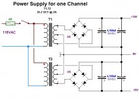
A quick PS schematic is attached.
I am looking over the amp schematic next.
It looks like the peeing contest is on!
To "throw a wrench in the works" I have the following to add.
In looking over all this stuff it appears to me that no matter what using solid state components is going to look like I used "solid state" components. Since I feel that I can still work this "aesthetic" into the system I want to put together and since my electronics knowledge is focused primarily around vacuum tubes I think I will just do my own "interpretation" of an existing design.
I have an extensive "junk box" and supplies of oddball stuff so while I am thinking to build something like this:
click here
I can purchase the board for about $50 delivered and source the other components as needed.
The suggested PS for a stereo amp into 8 ohms is a 25V 300VA tranny.
I am thinking that four 50-60VA trannies with sufficient capacitance would work? One tranny for each Pos. & Neg. supply per channel?
A quick PS schematic is attached.
I am looking over the amp schematic next.
Attachments
ooh,
The PSU schematic doesn't look right.
Should the CT's be left out altogether? This is what I was thinking originally.
The trannies are actually 25.2VCT @ 2A so that is 50VA?
So 100VA with 2 trannies per Channel.
You have to forgive me because I rarely work with Bridges and dual supply circuits, all my other stuff is TUBEs and I work from B+ to ground using Full Wave tube rectifiers.
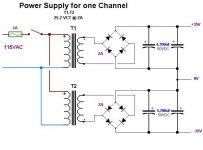
As re-drawn it should be OK?
So 100VA with 2 trannies per Channel.
You have to forgive me because I rarely work with Bridges and dual supply circuits, all my other stuff is TUBEs and I work from B+ to ground using Full Wave tube rectifiers.
As re-drawn it should be OK?
Assuming I work out the PS issues.
I revised the schematic on that project removing the bridging and SIM optional components.
Couple of questions
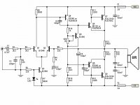
#1 Feedback resistors and caps are they R5,R4 and C3??
These determine overall gain and LF cutoff correct?
#2 How to increase Input Impedance (to about 50K min) and assuming I have no DC from the source and the source is cap coupled to prevent DC back into it can I remove C1? and what is the purpose of C2?
#3 Notes say that C4 determines HF responce this will be a SUB amp so what components determine that POLE so I can lower it?
Any help to a "Bottlehead" would be greatly appreciated!!
I revised the schematic on that project removing the bridging and SIM optional components.
Couple of questions
#1 Feedback resistors and caps are they R5,R4 and C3??
These determine overall gain and LF cutoff correct?
#2 How to increase Input Impedance (to about 50K min) and assuming I have no DC from the source and the source is cap coupled to prevent DC back into it can I remove C1? and what is the purpose of C2?
#3 Notes say that C4 determines HF responce this will be a SUB amp so what components determine that POLE so I can lower it?
Any help to a "Bottlehead" would be greatly appreciated!!
Attachments
How did you go from P2P chipamp to ESP 3A?? And why?
Hi MJ!
Methinks he wants high-current design like his tube amp.
As to function, my only guess is that maybe the discrete design will make for an easier time with a unified volume control, since the discrete design is easier to mod because it isn't sealed inside a chip.
Last edited:
Assuming I work out the PS issues.
#2 How to increase Input Impedance (to about 50K min) and assuming I have no DC from the source and the source is cap coupled to prevent DC back into it can I remove C1? and what is the purpose of C2?
#3 Notes say that C4 determines HF responce this will be a SUB amp so what components determine that POLE so I can lower it?
Any help to a "Bottlehead" would be greatly appreciated!!
Power supply looks correct (oops, bottom bridge is upside down!) .
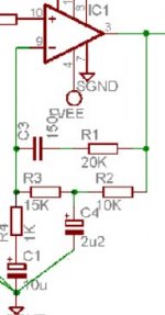
Input impedance: Change R2 to ~50K, change R5 to match and adjust R4 to get the same ratio (22:1). C2 is part of the input low pass filter, it's a good idea to maintain this.
Lower C4 (NO!) or lower the HF response?
Well, then, are these decent examples?:
Page 9 http://www.st.com/stonline/products/literature/ds/1460/tda2040.pdf
Page 10 http://www.st.com/stonline/products/literature/ds/1585/tda2052.pdf
Page 10 http://www.st.com/stonline/products/literature/ds/1459/tda2030a.pdf
which parts of pages 9 & 10 show that you understand how it works?
Those three links are all different files with different examples. Funny question, and the answer is that they show usage, but not especially good at showing why. Given several examples, with all different crossover points, it becomes more clear on what makes function.
Actually I have a better question: is that a passive or an active filter?
They are passive filters. Those designs really do need a unity stable quad op amp as a buffer instead of too-much reliance on those resistor mixers.
Now, THIS is an active filter (photo):
Attachments
They are passive filters. Those designs really do need a unity stable quad op amp as a buffer instead of too-much reliance on those resistor mixers.
Nope, those filters are active. Passive filters are made with passive parts. This is my last post here. I'm sorry for the offtopic, but I cannot help when I see electronics engineering being insulted by those who do not understand it.
Nope, those filters are active. Passive filters are made with passive parts. This is my last post here. I'm sorry for the offtopic, but I cannot help when I see electronics engineering being insulted by those who do not understand it.
Clarify please. Putting an amp at the output of passive filtration makes an. . . active filter? Wow, there are unexpectedly vast differences in quality of active filters.
- Status
- This old topic is closed. If you want to reopen this topic, contact a moderator using the "Report Post" button.
- Home
- Amplifiers
- Chip Amps
- Simple Chip Amp for P to P wiring