Hello,
I’ve been thinking to built some simple amp for my DT770(250Ohm) headphones. But I need a little help. The gain stage is provided by OPA1612 and buffer is NJM4556AD. 4556 is in the loop at the first schema but I'm concerned by the low slew rate which is 3V/µs.
There is my questions, will this affect the 1612? Or I should use second schema? There is paralleled buffer stage after the gain stage, which is very similar to O2. Or there is a possibility to paralleling 4556 in first schema?
Thanks for help.
It is advised that the small-signal bandwidth of a buffer within the loop be at least 3 times main amp small-signal bandwidth divided by overall noise gain.
OPA1612 has like an 80 MHz GBW and 40 MHz fT while being run at a gain of 3, while NJM4556AD is an 8 MHz part. Now even 40 MHz / 3 clearly is not < 3 * 8 MHz, so that won't work out without some local feedback across the 1612 to reduce GBW, usually in the form of a small capacitor. The combination of these two particular parts strikes me as a bit odd in general.
There is no reason why you couldn't parallel NJM4556As inside the loop as well though.
Both kinds of circuits have their pros and cons, in the loop is more problematic in the stability department while out of the loop may be (but does not have to be) less good in terms of noise and distortion. Speaking of which, those feedback resistor values seem excessive for an ultralow voltage noise part like the OPA1612. You do the math on what happens with a 1.7 pA/sqrt(Hz) current noise density.
The OPA1612 would in fact be expected to do a decent job driving 250 ohm headphones assuming you gave it some output series resistance (going by overshoot graphs, I'd say 22 ohms would be fine) and had some rather more than decent supply decoupling. That's always the crux with these low-Iq parts. Actually they've got the OPA1622 that's better suited for headphone driving duties, it's just in a stupid tiny package.
If I were to do this, I'd probably run a discrete single-stage Class A/AB buffer (or something BUF634-ish), with the opamp biased into Class A with about 5 mA or so. Not quite so simple any more, of course, but something that could perform really well.
Quad style 'Current Dumping" to combine fast opa and slow current buffer?
'simple' components, but needs precision trim to balance the AC Bridge relation between feedback and output combiner parts
some lite reading on the theory:
https://web.archive.org/web/20060221012225/http://quad405.com/jaes.pdf
the sim sticks antiparallel diode pair in series with the U2 'current buffer' to show the feedforward correction action
U2 could be the slow njm, or paralleld unity gain op amps
in practice the unity buffer would connect direct to the R3, L1 node
Attachments
Last edited:
DT770 is 96dB SPL at 1mW, so 100mW is 116dB which is very loud; would you need more than that?
100mW in 250 Ohms is 5V RMS, so 7V 28mA peak.
It appears the OPA1612 at +/-10V will drive the load well.
Yeah, the DT770 is not very hungry. I dont want more than that. I wanted that in case I want to use different headphones which will be more demanding.
It is advised that the small-signal bandwidth of a buffer within the loop be at least 3 times main amp small-signal bandwidth divided by overall noise gain.
OPA1612 has like an 80 MHz GBW and 40 MHz fT while being run at a gain of 3, while NJM4556AD is an 8 MHz part. Now even 40 MHz / 3 clearly is not < 3 * 8 MHz, so that won't work out without some local feedback across the 1612 to reduce GBW, usually in the form of a small capacitor. The combination of these two particular parts strikes me as a bit odd in general.
There is no reason why you couldn't parallel NJM4556As inside the loop as well though.
Both kinds of circuits have their pros and cons, in the loop is more problematic in the stability department while out of the loop may be (but does not have to be) less good in terms of noise and distortion. Speaking of which, those feedback resistor values seem excessive for an ultralow voltage noise part like the OPA1612. You do the math on what happens with a 1.7 pA/sqrt(Hz) current noise density.
The OPA1612 would in fact be expected to do a decent job driving 250 ohm headphones assuming you gave it some output series resistance (going by overshoot graphs, I'd say 22 ohms would be fine) and had some rather more than decent supply decoupling. That's always the crux with these low-Iq parts. Actually they've got the OPA1622 that's better suited for headphone driving duties, it's just in a stupid tiny package.
If I were to do this, I'd probably run a discrete single-stage Class A/AB buffer (or something BUF634-ish), with the opamp biased into Class A with about 5 mA or so. Not quite so simple any more, of course, but something that could perform really well.
Thanks for explanation, it makes sense. I have to learn a lot yet. I actualy have one piece of 1612 and few 4556. So I wanted to use them somehow. I didn't realize that those 20k in feedback will affect noise too much. Actually the 1612 is more available in czech republic than 1622 and I dont even have equipment for those tiny packages. The buf634 is good idea and it is simple.
'simple' components, but needs precision trim to balance the AC Bridge relation between feedback and output combiner parts
some lite reading on the theory:
https://web.archive.org/web/20060221012225/http://quad405.com/jaes.pdf
the sim sticks antiparallel diode pair in series with the U2 'current buffer' to show the feedforward correction action
U2 could be the slow njm, or paralleld unity gain op amps
in practice the unity buffer would connect direct to the R3, L1 node
Thanks, but I think that I leave this idea with slow 4556.
I actually like the idea to replace 4556 with Buf634. So I changed the schematic a little. Changed some values and add biasing resistor. I know that it is not the best solution. Diode or j-fet with resistor would be better? I remeber that it was called current limiting diode if I am not wrong.

Njm4556 should be replaced with a high speed op amp such as lm6171, and you have to add a capacitor between the inverting input and the output of the opa1612 to ensure the stability. The value of that capacitor can be found using trial and error method in simulation. You can search for phase margin simulation in the forum for more information.
So I changed it a little. I am only afraid that +-6V power supply will not be enough. I have a small circuit so I don't have to do anything new.

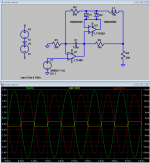
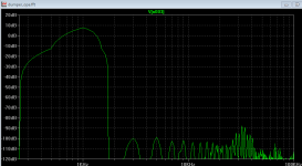
There is phase margin simulation, I hope I did it properly.
Open loop:
The green curve is without cap. Without it there is only 28° phase margin. With 220pF it is 57° which is better.


Closed loop:

without cap

with cap

There is phase margin simulation, I hope I did it properly.
Open loop:
The green curve is without cap. Without it there is only 28° phase margin. With 220pF it is 57° which is better.
Closed loop:
without cap
with cap
Last edited:
Hi, so I moved from the schematic to the real design. That was only first test without proper power supply and without biasing. Actually I will use the amp with +/-8V supply, which i found enough for my use. I was really suprised how it actualy sounds with the DT770 and with good source it plays realy nice. I dont have much time now to complete it, but i am looking forward to see if biasing improve the sound.


Little bit spamming my own thread
Anyway, this is the latest version of schematic, which is what I actually builded.
View attachment 645554
Completed amp with enclosure.
View attachment 645555
Nice amp! And the black PCB looks the part as well.

What was your reasoning for including Q1?
If you have the equipment, it would be really interesting to see if it improves (or decreasesIdiosyncrasy: Thanks, the main reason was for biasing to class A with 5mA.
) the measured performance for the OPA1612. If I recall correctly, it can go either way depending on the particular op amp and the rail that you use. Would certainly be useful information for others here.- Status
- This old topic is closed. If you want to reopen this topic, contact a moderator using the "Report Post" button.
- Home
- Amplifiers
- Headphone Systems
- Simple bufferd headphone amp