djk said:
Not sure here, but try grounding the shaft of the pot. I've had problems with something like this before, hope you find it. Sounds ground related in any event.
Shaft of pots are plastic...
The Pots were working without noise on two other amplifiers. Doesn´t problems with grounding always appear as 50/60Hz noise? This noise has much higher frequency and it has very high voltage for noise...
I just tested the "modded simple amp" with two channels powered, but only one connected to a subwoofer (8Ohm).
Unfortunately the channel with the sub did play only for 2 seconds with loud music...then it blew. The other channel is ok, of course.
Playing with the same power supply with no speaker is no problem - playing with approx. 1-2 Watt and speakers connect is also no problem.
What can I do to fix this problem?
Seems it is not a heat-problem, because of this short time playing...
Are oscillations the problem or something else (should the amp be limited in any way - use bigger resistors connected to the TIPs)?
I will post a list of the defective parts, when found...
Please help...I´m just going slightly mad... :-(
I just checked the blown channel.
The TIP142 is completely shortened and the TIP147 also doesn´t look much good (other values compared to new one) but isn´t completely shortened.
All other parts are all right.
When unmounting the channel I noticed the lead to the +45V rail wasn´t screwed firmly to the luster terminal. This could be due to vibrations/transport. So I am not sure, that there wasn´t a loose contact on the +45V rail.
Could this destroy both the TIPs and that be all my problem?
Hi Technics,
I did also use the TIP 142 / 147 in the past. And I can tell you the safety margin of these transistors isn't that big in an amp like this!
How large are your heatsinks?? (You said before you have tested them without heatsinks, you must use them)
How large is the voltage across the emitter-resistors (with no source connected)? Oscillations can occur this problem, but I don't think that would be the problem...
The problem I had in the past with these TIP's was the quiescent current, now I use the TIP's as drivers for one or more pairs of other powertransistors (i.e. BDV66/BDV67).
best regards,
HB.
hugobross said:
How large are your heatsinks?? (You said before you have tested them without heatsinks, you must use them)
How large is the voltage across the emitter-resistors (with no source connected)? Oscillations can occur this problem, but I don't think that would be the problem...
The problem I had in the past with these TIP's was the quiescent current, now I use the TIP's as drivers for one or more pairs of other powertransistors (i.e. BDV66/BDV67).
I only tested the amp at low power without heatsinks. When trying at high power I used a heatsink of approx. 15cm*20cm*2cm with a ventilator mounted on it. It should do the cooling right. But this wasn´t the problem, because the TIPs did blew in just 2 seconds - mechanical they seem all right, but they are shortened.
I didn´t measure voltage over resistors, but next time I will and then post it here.
Could you please post a schematic of your amp using the TIPs as drivers?
http://www.diyaudio.com/forums/showthread.php?threadid=12459
please read the comments on it, I didn't had the time to draw a new circuit....
i also want to replace the 12V zener into a LED or something, then the values of some resistors will change too...
place a 100 ohm resistor between the emitters of the drivers (TIP142-147).
best regards,
HB.
please read the comments on it, I didn't had the time to draw a new circuit....
i also want to replace the 12V zener into a LED or something, then the values of some resistors will change too...
place a 100 ohm resistor between the emitters of the drivers (TIP142-147).
best regards,
HB.
Did you put the thermal biasing diodes on the heatsink also? without doing this the amplifier will go into thermal runaway = increasing bias through output stage = bang.
You would be much better using power transistors such as MJ15003/4, MJ15024/5 or MJL21193/4 as suggested, with driver transistors such as MJE15030/1 or TIP29C/30C.
Overall I think you would be better building something a bit better and reliable. http://www.ampslab.com/c200.htm is a good starting point if you want to try something based around cheap and easy to get parts.
Hi guys,
don't you look closer when the last post was made.... it's over 2 years ago...
BTW user "hugobros" was last seen online here on DIYAudio 206 days ago and user "technics" (the person who started this thread) was last seen online 272 days ago... feels a bit someone trying to wake up a "dead", eg. kind of a meaningless attempt, but I wont stop you...
Sorry for being OT.
Cheers Michael
I made it once, but really i could not remember the problem it has.
I am not sure,but i thing was biasing problems and output heavy oscilations that did not stopped with enormous capacitors from base to colector....yeah!,... the wiring was short, around a inch, because those ones have enormous gain (darlingtons)
I am still interested.... all i can remember is that i have completed the schematic, because there are faulting filtering, rail resistors, and some capacitors...the circuit tried was more complete and standard, made using the more standard circuit techniques that we can see in our forum and in products schematics.
I am still interested in this circuit... simple, fast and easy to assemble...i love those things....minimun circuits, producing reasonable sound.... i will read last thread messages, since the day it disappeared from the main page...to see if someone had success with this one...i wanna try it once again.
And the time to do it if now or the dead line is yesterday!
I am talking about the first schematic published, not the transnova or other suggestion made.... the simple amplifier using TIP142 and TIP147...with VAS made with TIP41 and a differential input...a minimized standard amplifier.
Symassym4 worked nice with TIP3055 and TIP2955, so, the guy that want to use a good stock of 2N3055 and 2N2955 can use it there.
Also, using a BD139 and BD140 you can produce your own audio darlington, for 115 or 230 watts dissipation...for 10 or forn 20 amperes maximum current...but voltage limits will still the same...just connect them the same way transistors are connected inside the darlington chip, including two resistors and one diode each construction.
2N3055 and 2N2955 can go everywhere, the limits are the voltage that cannot be more than 100 volts...so the rails cannot be more than 50 volts.... the power cannot exceed 100 watts(dissipation power, sometimes twice the audio power produced), and the current cannot exceed 10 amperes...safe to use is 5 amperes, 20 Volts and 100 watts each transistor...but it can hold much more... as this safe limit is to last whole ethernity plus a half of the same ethernity.
There are pre conceptions because its hi frequency operation...limited to 3 Mhz..... well..i cannot hear that frequency, but also they tell us that the 10 kilohertz waveshape will be a little bit distorted because not a hi frequency transistor... well...well....well.... hear it and tell me if you increasing just a litlle the treble, if it will sound alike another one with high speed transistors or not!
I agree...both amplifiers, one using 2N3055 and other using higher speed units.... you will perceive immediattely that 2N3055 is mufling the sound...but try to advance the treble control, that may drive the 2N3055 amplifier , to 3 O'Clock...and now?
- Are you crazy Charlie?.... and the waveshape?
answer.... a _ell with the waveshape, i am not an scope!...i am human!!!.... and ... watch what speaker do with your waveshape that you will not worried about waveshapping any more!
regards,
Carlos
I could not attach the "Speedy Woofy"...this old guys cannot face our exigences
Speaker is a real big problem...people is painting it gold, red, having brigh surfaces, with waving shapes, cuts, bubbles, explendid magnets to smash foot fingers and holder to hand those monsters..rubber cushions... carbon fiber...titanium...and oils to avoid too much heat.... coils made with square section wiring...aluminium coils... refrigerated coils.
But still the same sheet (sheet of paper where you can see all the lyes printed there...ressonances and all stuff....but nothing is precise, it cannot reproduce all the waving of some music...this is almost impossible to big weigth..big masses in movement.
We have....we.... music lovers, diy experimenters, researchers, scientists....we have to find some solution to this problem, as the Speaker forum will never do that, as they did not perceive how bad the speaker are...problems related passion that blind us completelly.
Speaker need to have enormous changes, because now a days, continue to be the old "air pump"...very ridiculous thing mooving and pumping air.
If someone of you guys, had success constructing the basic schematic shown in this thread beginning... please, send it to me..the one that worked in real world.
nanabrother@yahoo.com
regards,
Carlos
Attachments
Ultima Thule said:Hi guys,
don't you look closer when the last post was made.... it's over 2 years ago...
It's still useful for any "newbies" who are reading the posts looking for ideas or simple circuits to try
jaycee said:
It's still useful for any "newbies" who are reading the posts looking for ideas or simple circuits to try
Yes, you are right!
Maybe I reacted more due to "fraga" who made a suggestion/statement(?) in a thread that has been dead for over 2 years, thats meaningless, eg. nowbody have asked for any help which I think anybody is capable to do when so needed.
It's just that it's a bit boring seeing lot of old, dead threads popping up in the top, when one goes through "todays" postings one should expect sensible reasons behind a posting and not lot of "blanket statements" and "one liners" etc. etc. to old threads where nobody is asking for anything for years, eg. I would like to see "quality" before "quantity" postings on this superb forum.
Well, that's just me, no offence to anyone, at least "fraga"!
However, I think I have made my point of view and constructive critic clear and think it's now way OT, so I'm going off this thread now.
Cheers Michael
djk said:"Hmmm, I have got plenty of 2n3055/MJ2955... do you have any circuit for them with power over 100W/8 Ohm?
They should work good for amps, I think...not as powerful as the mentioned above, but quite like the TIPs?"
Motorola(ON Semiconductor)2N3055/MJ2955 can make a good amplifier.
Rail voltages should be limited to ±30V, they are only rated at 60V. If you bridge two amps built with one pair per channel it will put out 120W/8R~150W/8R depending on how 'stiff' the supply is. You will need two pair per channel(eight outputs total)to drive 200W/4R~250W/4R.
I would try and get the MJ21193/21194 parts instead. In the USA eight 2N3055/MJ2955 cost the same as four M21193/21194, and you only need four of the M21193/21194 to make a 150W/8R, 250W/4 amplifier running on ±60V. And no need to bridge either.
The other problem I see is with the 2N3055, how fast is it? Budget or no-name 2N3055s are usually slow, they're intended for power supply work so that's OK, but they won't work well for an audio amplifier.
If you need 100W or more, the M21193/21194 are hard to beat on a watt/$ basis.
Do you have a schematic of such an amp, I am not that familiar with this stuff and I would very much appreciate your help
pinkmouse said:The Transnova patent schema
I've seen that schema on amps since the middle 90's, specially on guitar and bass amps.
Be aware that for stereo you need two completely separate power supplies.
Another issue is that the whole supply is "floating" with audio frequencies at full output voltage. Not good for nearby preamplifiers too.
On the other hand, it simplifies the output and driver stages, but also keep in mind that the voltage amplification occurs entirely in the output power stage.
astral_projecti said:
Do you have a schematic of such an amp, I am not that familiar with this stuff and I would very much appreciate your help
See MJL's latest thread :
http://www.diyaudio.com/forums/showthread.php?s=&threadid=119958
He's working up a big conventional amp using the 21193/4 pairs and +/-70V. The design looks solid and simple.
If anyone is still interested in "what to do with all these 2N3055's" I'm working up a big 200+ watt per channel amp using only general purpose transistors. The deisgn being considered at this point is cascoded and bridged, using 24 cheapo outputs per channel. I've collected a bunch of 60 and 80 volt power devices over the years, and looking to do something with them that's more than 30 w/ch. The last of the design tardeoffs is to decide quasi-comp (anp put up with potential problems) or full comp (that requires PNPs). So I let you guys help decide - which would be better for such a "junk box special" project?
wg_ski said:
If anyone is still interested in "what to do with all these 2N3055's" I'm working up a big 200+ watt per channel amp using only general purpose transistors. The deisgn being considered at this point is cascoded and bridged, using 24 cheapo outputs per channel. I've collected a bunch of 60 and 80 volt power devices over the years, and looking to do something with them that's more than 30 w/ch. The last of the design tardeoffs is to decide quasi-comp (anp put up with potential problems) or full comp (that requires PNPs). So I let you guys help decide - which would be better for such a "junk box special" project?
I am interested, that's why I previously asked about some help. Can you share some of your work?
astral_projecti said:
I am interested, that's why I previously asked about some help. Can you share some of your work?
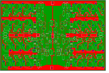
So far it looks like this. I still need to scrub one miserable inch off the board layout so it will fit in a 9x12 presensitized board. Schematic will follow in a couple of days when it's all worked out. It's using full complementary - I decided against trying this all-NPN. And I have lots of 60 and 80V PNPs at my disposal. The idea is this layout will do stereo with up to +/-55V rails using 60 volt junk (except the VAS). Or *bridge* using a single 100 to 110 volt supply.
It's not exactly 'simple', but it will use up a bunch of stuff that's otherwise just taking up space and can't be used for anything serious.
Attachments
- Status
- This old topic is closed. If you want to reopen this topic, contact a moderator using the "Report Post" button.
- Home
- Amplifiers
- Solid State
- simple Amplifier?