Hate to bump such an old thread 😂
I recently built one of the currawong amps. It come up a treat and sounds quite good. For the price and ease of assembly it’s a good bit of fun.
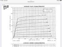
But I have come across an issue with the biasing resistors? The 330ohm 5watt resistors get so hot they smoke 😂 the voltage going to these bad boy’s constantly rises to excess of 63v. The book says there should be 22v across them?
I’m struggling to find out what’s causing this, any ideas would be greatly appreciated!!
Cheers guys
I recently built one of the currawong amps. It come up a treat and sounds quite good. For the price and ease of assembly it’s a good bit of fun.
But I have come across an issue with the biasing resistors? The 330ohm 5watt resistors get so hot they smoke 😂 the voltage going to these bad boy’s constantly rises to excess of 63v. The book says there should be 22v across them?
I’m struggling to find out what’s causing this, any ideas would be greatly appreciated!!
Cheers guys
Hard to know what the problem is if it sounds OK.
Do both channels have the same problem? If they do, it suggests a wiring error that is common to both channels.
Does the HT remain around 308V while the voltage across the bias resistors increases? Are the cathode bypass capacitors the right way round?
Check that the connections to the output transformer, both primary and secondary, are all correct. If the output is back to front the amp would become an oscillator but then it wouldn't sound good.
If the bias resistors are carrying 190mA the output valves won't be very happy either.
Thanks for the reply,
Yeah both channels do the same thing, audio quality never changes stays really good no noise or hum.
The HT is rather high, around 324v possibly too high? Capacitors are the correct way around.
I’ve checked the OP trannys, all wiring seems to be okay.
Yeah the OP valves do run hot but without a temp gun I can’t tell how how they are.
That difference in the HT shouldn't cause a problem. Given the variation in the mains (where I live it can be anywhere from 320V up to 347V) you'd expect the HT to vary around the nominal value.
The screen resistors are definitely 47Ω and you haven't inadvertently switched the anode and screen connections?
You could try emailing Silicon Chip. I've always found them to be responsive and helpful.
The screen resistors are definitely 47Ω and you haven't inadvertently switched the anode and screen connections?
You could try emailing Silicon Chip. I've always found them to be responsive and helpful.
How about the coupling caps to the output tubes' g1 grids?
What is the voltage to ground on all 4 g1, when the tubes are warmed up, and the cathodes voltage has increased beyond normal?
improperly specified maximum voltage on a coupling cap will degrade them.
If the B+ rises too much before the output tubes are warmed up, it might exceed the maximum capacitor voltage.
degraded or leaky caps may be the problem.
That is exhibited by the g1 grids' voltage to ground that is more than zero volts.
Or, really cheap output tubes can be gassy, they will go into thermal run-away, especially if Rg on g1 exceeds the maximum Rg resistance for the tube.
That is also exhibited by the g1 grids being more than zero volts above ground.
((63V)squared)/330 Ohms = 12 Watts dissipation. On a 5 Watt resistor?
Last edited:
hmm that’s a good point I’ll need to check that when I get home from work.
It’s possibly the tubes are not great either they are just cheapys.
I believe the resistors there are two of them are wired in series giving 660ohms at 5 watt.
It’s a weird fault, but a leaky cap could very well be causing an increasing voltage too! It’s drawing more current on the ht side than it should be too. It’s up around 1.2amps when it should be far lower I’d assume.
What are your output tubes?
6L6GC?
They are robust, with 30 Watt maximum plate dissipation, and screen maximum ratings of 450V and 5 Watt dissipation.
6L6, 6L6-G, 6L6-GA, and 6L6-GB?
19 Watt maximum plate dissipation, and screen maximum ratings of 270V and 2.5 Watt dissipation.
Easy to exceed some ratings, and go into thermal run-away.
47 Ohms screen resistors and 324V does not sound good for these earlier 6L6s.
Is there a complete and accurate schematic of the amplifier and power supply.
Could be handy in solving the problem.
For self bias, the maximum Rg resistor is 500k Ohms (0.5 Meg Ohm).
Last edited:
A couple of weeks ago, I drove over to Eurotubes.com.
I picked up 2 6L6GC, 2 5881, and 2 EF806S, and 2 6V6S.
They are all Extensively re-tested, and very well matched.
I have been purchasing there for a very long time.
You can order yours online: link eurotubes.com.
They ship to many countries.
Almost 2 decades ago, I used to get Electro Harmonix tubes when I went to CES (Consumer Electronics Show), in Las Vegas.
I purchased them from a New York company that was at the show.
I also purchased David Chesky's CDs at CES, direct from David and his brother.

Yes, have to agree that they're a good company to deal with. Also, their shipping to Canada is quick (though driving over is quicker 😁)A couple of weeks ago, I drove over to Eurotubes.com.
I picked up 2 6L6GC, 2 5881, and 2 EF806S, and 2 6V6S.
They are all Extensively re-tested, and very well matched.
I have been purchasing there for a very long time.
You can order yours online: link eurotubes.com.
They ship to many countries.
300 mA in EACH output tube? That’s about all you can get a 6L6 to pull without a driver transformer. It smells like g1 completely floating to me. Even with too high a g1 resistor it would stop short of 300mA if you’ve got cathode resistors.hmm that’s a good point I’ll need to check that when I get home from work.
It’s possibly the tubes are not great either they are just cheapys.
I believe the resistors there are two of them are wired in series giving 660ohms at 5 watt.
It’s a weird fault, but a leaky cap could very well be causing an increasing voltage too! It’s drawing more current on the ht side than it should be too. It’s up around 1.2amps when it should be far lower I’d assume.
If they are EH 6L6’s they are the GC variety. They make a 5881 too, which would be a lower power version. Usually a geetar amp would stick with the GC, and that’s mostly the market they sell into. They run them on more than 375 volts all the time.
wg_ski,
What cathode resistors, other than very low Ohms current sense resistors, the amplifier in question uses fixed bias.
300mA per output tube?
Fix the amplifier!
An AB1 amplifier with a 6000 Ohm p-p output transformer . . .
When one tube is cut off (AB1) then from center tap to one end of the primary is only 1500 Ohms.
300mA x 1500 Ohms = 450V (if the B+ was 450V, and IF the plate could go to Zero Volts, which it can not; so you will need a lot more than 450V B+).
Don't try to do this!
These are output vacuum tubes, not saturated NPN transistors with the Collector jumping through the Base, on its way to the Emitter (Base at 0.75V, Collector at 0.3V, and Emitter at Zero volts).
Sounds like either a guitar amplifier, or a TubeLab_com blow-it-up special!
(kind of the same thing).
Last edited:
Sorry, I’m still a bit of a novice 😂 What do you mean by G1 floating?300 mA in EACH output tube? That’s about all you can get a 6L6 to pull without a driver transformer. It smells like g1 completely floating to me. Even with too high a g1 resistor it would stop short of 300mA if you’ve got cathode resistors.
If they are EH 6L6’s they are the GC variety. They make a 5881 too, which would be a lower power version. Usually a geetar amp would stick with the GC, and that’s mostly the market they sell into. They run them on more than 375 volts all the time.
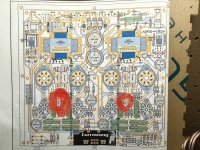
G1 should be connected to ground through a resistor. These are shown as 1 Meg in the layout but as 6A3Summer says in post #68, they should be no more than 500k. Try replacing them with 470k and make sure you measure 480k (470k + 10k grid stopper) between G1 (pin 5) and ground.
- Home
- Amplifiers
- Tubes / Valves
- Silicon Chip mag "Currawong" amp