The more I thought about Andrew's feedback, the more I could see that there was something very wrong with the higher frequency results. However, I couldn't see how his diagnosis - that the testing rig had insufficient feedback - could be right, given the test report for the sound card. Thinking about this overnight, I realised the problem - the use of A-weighting is what's causing the higher frequency results to be under-reported. So I've redone them all, with no weighting. I've updated the 2 comparison charts in-place, but here they are again for reference:

This chart now re-opens the question: what did SC actually test? To get the low THD at high frequencies, these results show that the amp has to be correctly biased. It also confirms that at lower frequencies, better THD than SC reported is possible.

The comparison between amps shows the same basic picture as before, but the measurements at 10k now show the unmodded SCULD as not being the clear runner-up any more.
This chart now re-opens the question: what did SC actually test? To get the low THD at high frequencies, these results show that the amp has to be correctly biased. It also confirms that at lower frequencies, better THD than SC reported is possible.
The comparison between amps shows the same basic picture as before, but the measurements at 10k now show the unmodded SCULD as not being the clear runner-up any more.
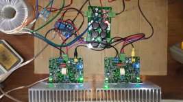
As promised, here's the schematic for the dummy load / voltage divider.

You can see that there's 2 binding posts for connecting red/black for the dummy load (i.e. from the amp's speaker terminals), and then 3 RCA sockets. You connect only one of those sockets at a time - which one you choose determines the amount of attenuation. You could use a switch instead with a single socket, but by not using a switch there's less opportunities for distortion.
There's really not much to show - the main point of interest is the choice of those 50W resistors at the input. They need to be non-inductive resistors. I used these: http://australia.rs-online.com/web/search/searchBrowseAction.html?method=getProduct&R=0118794 . The data sheet on that page shows how to pick a suitable heat sink. I used the Jaycar 150mm HS, which has the minimum required thermal resistance. For the smaller resistors I used these: http://australia.rs-online.com/web/search/searchBrowseAction.html?method=getProduct&R=3204716 . I'm sure you could get away with lower power ones for those smaller resistors - I just used what I had available.
I used two heatsinks, and put one of the 50W resistors on each. I then connected the two in parallel directly. The remainder of the resistors I shared across the two heatsinks. I put electrical tape under the solder points, to avoid accidentally shorting through the HS.
I then connected it all up directly with suitably thick wire for the signal, and screwed aluminium plates on each side. On one of the plates I put the sockets and labels for them.

I find that the heatsinks don't get warm at all. I guess the HS specs in the data sheet are for long term continuous operation. I would say you could very comfortably get away with half what they suggest, for this purpose.
I'll follow up later with a description of how to use this with appropriate software to measure your amp.
You can see that there's 2 binding posts for connecting red/black for the dummy load (i.e. from the amp's speaker terminals), and then 3 RCA sockets. You connect only one of those sockets at a time - which one you choose determines the amount of attenuation. You could use a switch instead with a single socket, but by not using a switch there's less opportunities for distortion.
There's really not much to show - the main point of interest is the choice of those 50W resistors at the input. They need to be non-inductive resistors. I used these: http://australia.rs-online.com/web/search/searchBrowseAction.html?method=getProduct&R=0118794 . The data sheet on that page shows how to pick a suitable heat sink. I used the Jaycar 150mm HS, which has the minimum required thermal resistance. For the smaller resistors I used these: http://australia.rs-online.com/web/search/searchBrowseAction.html?method=getProduct&R=3204716 . I'm sure you could get away with lower power ones for those smaller resistors - I just used what I had available.
I used two heatsinks, and put one of the 50W resistors on each. I then connected the two in parallel directly. The remainder of the resistors I shared across the two heatsinks. I put electrical tape under the solder points, to avoid accidentally shorting through the HS.
I then connected it all up directly with suitably thick wire for the signal, and screwed aluminium plates on each side. On one of the plates I put the sockets and labels for them.
I find that the heatsinks don't get warm at all. I guess the HS specs in the data sheet are for long term continuous operation. I would say you could very comfortably get away with half what they suggest, for this purpose.
I'll follow up later with a description of how to use this with appropriate software to measure your amp.
Silicon Chip Ultra LD Amplifier Mk II Mmmmmmmmm....
Hi
I'm at my wit's end trying to fix a 'hum' problem with a newly built amplifier based on the 'Silicon Chip Ultra LD Mk II' design. I'm new to the forum, however not entirely new to DIY electronics; this is my 4th amplifer project. Any hints or ideas on how to solve this will be greatly appreciated.
The situation is this:
I have built a stereo amplifier from 2 Ultra LD Mk II modules & power supplies both sourced from Altronics. I have added to this a pair of 300VA toroidial tx's and a speaker protection unit and fitted it all into a 3RU box myself. The application is a monitor amp for my kid's home recording studio. In this application, the 'preamp' is a Behringer 12 channel mixer. I built the amp as per the kit's instructions (which were excellent) and not withstanding all the interesting mods suggested here (this is a great forum...), the amplfier works, and sounds great.
However - there is an annoying amount of hum present.
How much hum? Well, I can't hear the hum while music is playing at a usual level, however in quiet passages and between tracks, there it is. It's a bit like going straight back to the late 70's, when I built my first amp!..., so my guess is the noise level is around -70 to -80dB. That seems to corresspond with the 7mV figure I get on my DVM (7mV/25V =
-71dB), however, I don't trust my DVM to measure AC voltages that low. As you can appreciate, my expectation for an amplifier speced at S/N = -127dB, is a lot higher than this.
Now, here is the really annoying bit. If I disconnect the amp, with no inputs it is quite - dead quite. If I connect ANYTHING however there is the hum again. And by anything I'm including:
1. A Pioneer PD-707 CD player
2. An RCA cable with an iPhone connected to it. Hard to think there is an 50Hz coming from an iPhone!
3. The RCA cable just by itself
4. A cable connected to the mixer's balance output with two wires in the core connected to the mixer's +ve & -ve and the -ve connected to the shield at the amp end.
5. A cable connected to the mixer's balance output with two wires in the core connected to the mixer's +ve & -ve and the -ve connected to the 0V at the amp end and the shield connected to an earth post on the amp.
Cases 1,2,3,4 are much the same, case 5 is much worse. Case 3 is weird - I fundamentally don't get it...
I've experimented with the amplifier too. I've tried replacing the 10ohm resister between the input 0 and earth with 47ohm and 0ohms, both were worse. In desparation, I have tried reducing the amplifier's gain. I did this by replacing the 12k feedback resister with 4.7k. You would think that taking 7.5dB off the amp would quieten it down, but it makes absolutely no difference.
I'm starting to think that the amp's CMRR is really no good and that I'm going to have to fork out for some balanced to unbalanced converters, but this just seems excessive for an amp which is just 0.5m from the mixer, in the same rack.
Any help, hints, advice, experiments from other members would be terrific.
there's a mistake in the PCB.
Can anyone remember which thread/Member discussed it?
Andrew
As the kits were supplied by Altronics,it is highly unlikely that there will be any problems with the kit supplied.Both Jaycar and Altronics supply amended photocopies of the original project, and also include Errata,construction notes etc. too , if available.
Alex
Last edited:
Hugh
I find 10R between the input signal ground and the chassis as expected. I'm not sure what you mean by 'star earth' however. I have carefully brought the toroidal centre taps and mains earth together to a single bolt on the chassis. Is the suggestion to put 10R & some diodes in series with the centre taps back to this earth point thus floating the whole power supply and amp off the chassis? By back to back diodes I presume you mean in parallel a to k so as to limit the float to 0.6V and as an alternative to the 10R?
Thanks for your help with this.
Regards
Greg
Yes, Greg, thought it was signal floated.
Sometimes it helps if star earth - that's the earth that the speaker grounds and star earth are attached to - it also linked via 10R and ak/ka diodes (as you describe) to chassis. This sometimes solves all the problems.
Did you check that RCA input ground was not connected to chassis?
Hope this helps,
Hugh
Hugh
I have some success to report. Following your advice (or at least my intrepetation of it - all errors are my own!) I have 'floated' both the amp's 0V from the chassis by removing the connection from the centre tap to the chassis. This has solved the hum problem completely. The amp is completely silent - the loudest noise to be heard is acually the windings on the toroidial tx's!
I wonder if there is any downside to this arrangement? My mains earth is still connected to the chassis, so I still have basic electrical safety. I guess the amp would not be so robust against a fault in a connected device.
In any case thankyou double plus for your help with this - having spent some considerable time on the project, it's a great relief to bring it to such a successful conclusion.
Best Regards
Greg
PS This forum is AWESOME!!
Electrobug,
IF chassis is connected to power (mains) earth, and IF the transformers are tested for double insulation to 4000V (the UL/CE standard), then it is quite safe to have star earth unconnected to chassis. HOWEVER, I'm suggesting here that star earth (amp power earth, trafo center tap and LS ground connections) should be connected to chassis via a 10R resistor and back to back diodes.
Usually, this chassis/star earth connection scotches any hum. Sometimes it does not, however, and in this situation with no connection between star earth and chassis the amp is effectively double insulated, like the majority of UL/CE approved appliances used in modern homes.
Hope this helps, and thank you for your very positive post, this forum is very good when people remain positive,
Hugh
Here is a report back. I have installed the 'back to back' diodes - two diodes in parallel a to k from the amplifier ground to the chassis 'star earth'. I am pleased to report that this has not affected the amplifier's excellent performance - hum and noise are still in-audible.
I (now) understand that these diodes provide electrical safety in the case of:
1: A toriodal tx insulation failure between the primary & secondary
2: An internal wiring failure where the dc has come in contact with the 240VAC - unlikely, 'cause I've tied 'em done real good.
3: An external wiring fault where 240VAC has come in contact with either the speaker cabling or input cabling
In all of these cases the diodes will conduct allowing a fuse, circuit breaker or in my case earth leakage circuit breaker to open, while stopping any current at below 0.6V.
I have also attached a photo of the finished amplifier for anyone else building one. As you can see, the whole stereo amp was fit into a 3RU, the arrangement kept the centre of gravity for the unit close too the front, in order to be nice to the case & my rack, and, as mentioned above, there was no compromise with regards to induced hum or noise.
Thankyou to all thread respondants for your positive encouragement.
Regards
Greg
Attachments
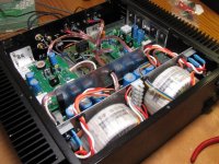
Thanks for that jamesfeline. I hope you liked the toothpicks holding the tranny primary wires in place ha ha ha!!!
The Silicon Chip Magazine boards are really well made and cheap! The support from the their team is also sterling!
I'm now onto the second module. I know the chassis will be the biggest challenge!
The Silicon Chip Magazine boards are really well made and cheap! The support from the their team is also sterling!
I'm now onto the second module. I know the chassis will be the biggest challenge!
- Status
- This old topic is closed. If you want to reopen this topic, contact a moderator using the "Report Post" button.
- Home
- Amplifiers
- Solid State
- Silicon Chip 200Watt LD amplifier