Are these 6 opamps discrete opamps? 24V is unusual for an opamp.
Jan
No they are a mixure of opa627 and opa604. Naim ran them at 18V but i upped it to 24V.
This cdp runs on positive voltage everywhere, no negative at all.
Dac chip power supply pins are digital, anologue and the third is for an internal opamp which is the pin that responds the best to better psu. There is no split re channels.
With the opamps and alwsr i found that getting them too close brought problems because of the regulators output looking inductive
Many thanks
Ringing i think, although i dont have an oscope to check. Sibilance on vocals (especially female) was how i noticed it. A longer supply wire between alwsr and opa627 seemed to reduce it.
I am no electrical engineer just a hobbyist looking for better music, learning as i go and having fun along the way. I have no measurement equipment apart from a DMM and my ears.
I have a lot of transformers in my system and as well as the EMI produced they take up an awful lot of space.
I am no electrical engineer just a hobbyist looking for better music, learning as i go and having fun along the way. I have no measurement equipment apart from a DMM and my ears.
I have a lot of transformers in my system and as well as the EMI produced they take up an awful lot of space.
I don't know details of the ALW regulators, but to some extend ALL regulators exhibit inductive behaviour at high frequencies. It is a natural effect of a regulator bandwidth falling with frequency.
Anything that shows a higher (output) impedance with frequency reacts as if it is an inductance. The trick is to design the regulator such that the effect doesn't react with the rest of the circuit.
How much is the current draw from that 24V supply? The SilentSwitcher can be customized for 24V but the max load is then 50mA. Should be enough for 6 opamps. Are they single opamps?
So with a pair of SilentSwitchers you could have +24V 'analog', +5V 'analog' and +5V 'digital'. Very little space, very little heat, USB charger power or Power Bank operation, very high performance, very clean supplies.
Jan
Edit: if there are 6 OPA627 opamps with max supply voltage of 7.5mA each that is within the 50mA budget of a 24V SilentSwitcher. No problem.
Last edited:
Jan, there is at least one regulator which does not exhibit inductive behavior at high frequencies. It is a natural effect of a transconductance amplifier's bandwidth vs frequency roll off. When you build a shunt regulator using a TA as the regulating element, output impedance does not rise with frequency. It falls. Work through the block diagram in the Laplace domain, it's an elegant surprise.
The regulator I'm speaking about is the "Simplistic Salas Shunt Regulator v1.3 ultra-BiB" and many many of them have been built and sold here on diyAudio; I think they're on Group Buy #5 or thereabouts (!). The transconductance amplifier has two stages, a common base stage feeding a common emitter stage, so the transconductance of the cascade is very high. High gm means the frequency compensation network can be realized with widely available, standard value, low cost components. It's very cute.
The regulator I'm speaking about is the "Simplistic Salas Shunt Regulator v1.3 ultra-BiB" and many many of them have been built and sold here on diyAudio; I think they're on Group Buy #5 or thereabouts (!). The transconductance amplifier has two stages, a common base stage feeding a common emitter stage, so the transconductance of the cascade is very high. High gm means the frequency compensation network can be realized with widely available, standard value, low cost components. It's very cute.
I don't know details of the ALW regulators, but to some extend ALL regulators exhibit inductive behaviour at high frequencies. It is a natural effect of a regulator bandwidth falling with frequency.
Anything that shows a higher (output) impedance with frequency reacts as if it is an inductance. The trick is to design the regulator such that the effect doesn't react with the rest of the circuit.
How much is the current draw from that 24V supply? The SilentSwitcher can be customized for 24V but the max load is then 50mA. Should be enough for 6 opamps. Are they single opamps?
So with a pair of SilentSwitchers you could have +24V 'analog', +5V 'analog' and +5V 'digital'. Very little space, very little heat, USB charger power or Power Bank operation, very high performance, very clean supplies.
Jan
Edit: if there are 6 OPA627 opamps with max supply voltage of 7.5mA each that is within the 50mA budget of a 24V SilentSwitcher. No problem.
Hi Jan,
Thanks for your advices, much appreciated.
Yes they are single opamps. There are two OPA627 and four OPA604. I have only measured the current draw of the whole output stage including the two ALW super regs I have in there. I will have to have a look in my notes to remember what it is (was a while ago).
Anyway, I don't have to run them at 24V. Naim designed the supply at +18V using LM317 and I already had super regs built for +24V as that voltage is often used by Naim in preamps, phono stages etc. I saw no point in changing them down to 18V so installed them at 24V. So I could run them at the original 18V if need be.
Excuse my use of the wrong terminology at times, being untrained all my electronic knowledge has been learned from the web.
I am also interested in when several different loads are put on a silent switcher can these loads still modulate each other as with a traditional transformer, rectifier etc ? I have gone to great lengths in my modifications so far to give various parts of the cdp their own independent psu, right back to the transformer. I have found it to be very rewarding as regards the music I am getting out of this 20 year old CDP and I have learnt a lot in the process.
I have a 200VA toroid doing digital duties, a 3VA EI on a fancy clock, 500VA twin secondary toroid for the six opamps, relay etc in the output stage, and three more 3VA EI transformers - one for each DAC power supply pin. As you can see there is lots going on here and that's not mentioning all the super regulators, capacitance multipliers and modified LM317's.
Many thanks, Stuart.
Having completely separate transformers, rectifiers, reservoir capacitors is good thinking. It avoids that the various loads mutually influence the power at their supply points.
But it only gets you so far. Those separate supplies each have their own shortcomings, and to solve those more drastic measures are needed.
Superregulators, in whatever shape, are a good solution, but then you still have to drag transformers, rectifiers, reservoir caps along.
And look at the power situation. In your example, looking only at the opamps, at 18V and say 45mA total they consume just 810mW. Hell, the waste in a typical transformer is several watts doing nothing. Then there's losses in the rectifiers and the regulator pass devices. Lots of heat in the box.
You may know that I have dabbled in superregulators and my design is still available in the diyaudio store. But with the SilentSwitcher I made another step. USB chargers (and the internals in a Power Bank) are engineered for 90+% efficiency, so very little loss and very little heat. And they are a first wall between the mains and the outputs. And the USB adapters are tiny compared with transformers etc. and can be put out of the way, at the mains plug.
It only became possible with the development of low dropout very fast very low noise regulators for cell phones. These attenuate incoming noise and junk a factor of 80dB (10,000 x) up to 1MHz. Read that again. 1MHz. They are awfully quiet as can be seen in the noise graph I posted a few posts back.
They work great with only 0.4V overhead, which means they run very cool. And that became possible with another breakthrough by the smart engineers at LTI (now ADI): a switcher that runs at 1MHz with extremely low switching residue (which then is attenuated 10,000 by the linear reg downstream).
Third factor is a way I found to layout a PCB in such a way that rf stuff is contained in and on the board.
There you have it. A regulator that is a match for my super-regulator, but runs cool, is small and can run free from the mains.
Sorry for the diatribe but I am somewhat proud of this baby
BTW, In your case, if you decide to go for SilentSwitchers, I would chuck that LM317, not bad but no match for this stuff. Customize a SS for +18V, have another for +5V and run the 5V 'digital' from either of the SS's, I guess it won't need more than 1A?
Jan
Last edited:
Hi Jan,
I'm all in on a customized SS for +/-18V!
My Hans Polak ultimate phono stage need one badly!
I'm totally in love with the concept! Thx Jan!
I use SilentSwitchers for my turntable, phono stage, B1 rev. 2, G Word preamp and my dac. Only my power amp is connected to the grid.
No fuzz, no hum, no hiss... zip! Just 'blacker than black' background.
/Kim
Having completely separate transformers, rectifiers, reservoir capacitors is good thinking. It avoids that the various loads mutually influence the power at their supply points.
But it only gets you so far. Those separate supplies each have their own shortcomings, and to solve those more drastic measures are needed.
Superregulators, in whatever shape, are a good solution, but then you still have to drag transformers, rectifiers, reservoir caps along.
And look at the power situation. In your example, looking only at the opamps, at 18V and say 45mA total they consume just 810mW. Hell, the waste in a typical transformer is several watts doing nothing. Then there's losses in the rectifiers and the regulator pass devices. Lots of heat in the box.
You may know that I have dabbled in superregulators and my design is still available in the diyaudio store. But with the SilentSwitcher I made another step. USB chargers (and the internals in a Power Bank) are engineered for 90+% efficiency, so very little loss and very little heat. And they are a first wall between the mains and the outputs. And the USB adapters are tiny compared with transformers etc. and can be put out of the way, at the mains plug.
It only became possible with the development of low dropout very fast very low noise regulators for cell phones. These attenuate incoming noise and junk a factor of 80dB (10,000 x) up to 1MHz. Read that again. 1MHz. They are awfully quiet as can be seen in the noise graph I posted a few posts back.
They work great with only 0.4V overhead, which means they run very cool. And that became possible with another breakthrough by the smart engineers at LTI (now ADI): a switcher that runs at 1MHz with extremely low switching residue (which then is attenuated 10,000 by the linear reg downstream).
Third factor is a way I found to layout a PCB in such a way that rf stuff is contained in and on the board.
There you have it. A regulator that is a match for my super-regulator, but runs cool, is small and can run free from the mains.
Sorry for the diatribe but I am somewhat proud of this baby
BTW, In your case, if you decide to go for SilentSwitchers, I would chuck that LM317, not bad but no match for this stuff. Customize a SS for +18V, have another for +5V and run the 5V 'digital' from either of the SS's, I guess it won't need more than 1A?
Jan
Hi Kim,
Glad you are enjoying it!
Customizing for +/-18V involves removing 4 tiny SMD parts - easy, just heat one side and they come off.
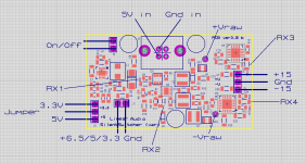
Then you need to solder 4 SMD resistors 1206 size, RX1 through RX4 in the attached. These are relatively large, and a steady hand and a fine-pointed solder iron does it.
If you are game I will give the resistor values tomorrow.
Jan
Glad you are enjoying it!
Customizing for +/-18V involves removing 4 tiny SMD parts - easy, just heat one side and they come off.
Then you need to solder 4 SMD resistors 1206 size, RX1 through RX4 in the attached. These are relatively large, and a steady hand and a fine-pointed solder iron does it.
If you are game I will give the resistor values tomorrow.
Jan
Attachments
I'm all game, thank you!
I'll send you an e-mail.
/Kim
I'll send you an e-mail.
/Kim
Hi Kim,
Glad you are enjoying it!
Customizing for +/-18V involves removing 4 tiny SMD parts - easy, just heat one side and they come off.
Then you need to solder 4 SMD resistors 1206 size, RX1 through RX4 in the attached. These are relatively large, and a steady hand and a fine-pointed solder iron does it.
If you are game I will give the resistor values tomorrow.
Jan
Last edited:
Having completely separate transformers, rectifiers, reservoir capacitors is good thinking. It avoids that the various loads mutually influence the power at their supply points.
But it only gets you so far. Those separate supplies each have their own shortcomings, and to solve those more drastic measures are needed.
Superregulators, in whatever shape, are a good solution, but then you still have to drag transformers, rectifiers, reservoir caps along.
And look at the power situation. In your example, looking only at the opamps, at 18V and say 45mA total they consume just 810mW. Hell, the waste in a typical transformer is several watts doing nothing. Then there's losses in the rectifiers and the regulator pass devices. Lots of heat in the box.
You may know that I have dabbled in superregulators and my design is still available in the diyaudio store. But with the SilentSwitcher I made another step. USB chargers (and the internals in a Power Bank) are engineered for 90+% efficiency, so very little loss and very little heat. And they are a first wall between the mains and the outputs. And the USB adapters are tiny compared with transformers etc. and can be put out of the way, at the mains plug.
It only became possible with the development of low dropout very fast very low noise regulators for cell phones. These attenuate incoming noise and junk a factor of 80dB (10,000 x) up to 1MHz. Read that again. 1MHz. They are awfully quiet as can be seen in the noise graph I posted a few posts back.
They work great with only 0.4V overhead, which means they run very cool. And that became possible with another breakthrough by the smart engineers at LTI (now ADI): a switcher that runs at 1MHz with extremely low switching residue (which then is attenuated 10,000 by the linear reg downstream).
Third factor is a way I found to layout a PCB in such a way that rf stuff is contained in and on the board.
There you have it. A regulator that is a match for my super-regulator, but runs cool, is small and can run free from the mains.
Sorry for the diatribe but I am somewhat proud of this baby
BTW, In your case, if you decide to go for SilentSwitchers, I would chuck that LM317, not bad but no match for this stuff. Customize a SS for +18V, have another for +5V and run the 5V 'digital' from either of the SS's, I guess it won't need more than 1A?
Jan
Hi Jan,
No problem with the essay
Shows you are passionate about your product and very talented  Yes I think you should be proud of your baby.
Back to my CDP. The digital stages (before the dac) use roughly 400mA max but that is up and down constantly around that figure. Trouble is a couple of the LM317 regs (there were 16 of them in here originally !) supply 9V which may be a problem. They are for the two TDA7073AT dual power driver chips. Not sure why they need 9V but one of the LM317 regs also goes on to power the LM317 in the transport swing out tray so the laser effectively gets double regulation- firstly down to 9V and then from 9V down to 5V locally.
Found my notes on the opamps in the output stage. The two final opa627 opamps (one per channel) draw 15.5 mA. The proceeding four opa604 (two per channel) draw 60 mA according to my old measurements and calculation. I could possibly have made a mistake there but there are other circuits connected to the group of 4 opa604 which may be adding to the current draw (output relay and other stuff that I have no idea what they are).
I need to have a think. Would the current available from the SS for the opamps be increased if the voltage is decreased from 24 to 18V ?
Thanks for your time and advice Jan. It would be great to get rid of some of my linear power supplies. My system seems to breed them
Yes 60mA for the 4 opamps is a lot, so there must be other stuff hanging off that supply.
That 400mA from the 5V is no problem, SS can easily source 1A.
For a +/-18V SilentSwitcher you can count on 100mA per side.
I just completed the calculations for the 18V and 24V mods, next post. ;-)
Jan
That 400mA from the 5V is no problem, SS can easily source 1A.
For a +/-18V SilentSwitcher you can count on 100mA per side.
I just completed the calculations for the 18V and 24V mods, next post. ;-)
Jan
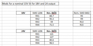
Mods to convert a customizeable SilentSwitcher (var) for +/-18V or +/-24V
Attached is the overview of resistors that need to be changed.
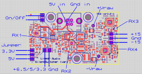
Note that the small SMD0402 resistors that are on the board need to be removed first. Just heat one side for a few seconds and you can then push them off. They are shown with a small blue cross.
Then solder the new resistors, which are larger SMD1206 so should be easy to do. Download the mod guide and follow that. There's a link to a short Youtube illustrating how to solder them. No special tools required, just a steady hand, a pair of tweezers and a pointed solder point. Best time of day is in the morning after your shower ;-)
To limit the risk of making mistakes, follow the prescribed order. First remove one resistor, solder the replacement new one, and measure the voltage as shown. It's really must faster than describing it.
Jan
Attached is the overview of resistors that need to be changed.
Note that the small SMD0402 resistors that are on the board need to be removed first. Just heat one side for a few seconds and you can then push them off. They are shown with a small blue cross.
Then solder the new resistors, which are larger SMD1206 so should be easy to do. Download the mod guide and follow that. There's a link to a short Youtube illustrating how to solder them. No special tools required, just a steady hand, a pair of tweezers and a pointed solder point. Best time of day is in the morning after your shower ;-)
To limit the risk of making mistakes, follow the prescribed order. First remove one resistor, solder the replacement new one, and measure the voltage as shown. It's really must faster than describing it.
Jan
Attachments
Last edited:
Hi Jan,
Can SilentSwitchers be paralleled to increase current handling or will they fight each other?
Thanks,
Nic
There are no provisions for that. Two SilentSwitchers will have minute small output voltage differences, and if you parallel them the one that is slightly lower would start to draw current from the one that's slightly higher. So that won't work, sorry.
Can't you use the two SS's to supply two units, like two channels on a preamp?
Jan
Can't you use the two SS's to supply two units, like two channels on a preamp?
I'm considering the possibility of using SS's to power the RTX6001 to get it off the grid. I did not investigate the supply structure of the analyser, but what is known is that it uses a Toroid with 15V-0, 15V-0 and 9-0 secondaries and that roughly 0.3A is drawn from each of these.
I guess that these are used to generate a bipolar analog "master" rail (maybe 18V-0-18V) and a digital "master" rail (maybe 11V-0), but this is all speculation for the moment.
I'm just trying to understand if one might get it to work with SS's, or if to think in another direction right away
I think this can only be answered if we have an overview of the voltage/current requirements. With the SS you can directly supply the regulated voltages so you can bypass any on-board regulators.
I will ask Jens if he is willing to give that info. But I think he will also point out that it voids the warranty.
Jan
There are at least 5 linear regulators on the RTX6001 board a 5V, a 6V, a 12V and two LM317-type.
- Home
- Vendor's Bazaar
- SilentSwitcher - mains-free +/-15V and 6/5/3.3V power