hello,
i've search around the forum but i was not able to find the answer.
i would like to buy a splitter for a line out level, to split the signal.
i have to split 1 input to 3 output
i would like something active, i was thinking about a buffer.
my output signal actualy is
* Rated output level: 4 dBm
* Output impedance: 1 kilohm or less
input is a mixer input, line in. tipycally 10 or 20Kohm
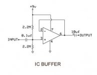
a buffer like the attached image should have a gain of 1.
i was wondering if i have to set gain to 3 (adding resistors in non-inverting mode), to be able to split the signal in three path, or it is not necessary.
thanks,
hOZONE
i've search around the forum but i was not able to find the answer.
i would like to buy a splitter for a line out level, to split the signal.
i have to split 1 input to 3 output
i would like something active, i was thinking about a buffer.
my output signal actualy is
* Rated output level: 4 dBm
* Output impedance: 1 kilohm or less
input is a mixer input, line in. tipycally 10 or 20Kohm
a buffer like the attached image should have a gain of 1.
i was wondering if i have to set gain to 3 (adding resistors in non-inverting mode), to be able to split the signal in three path, or it is not necessary.
thanks,
hOZONE
Attachments
hozone,
You shouldn't need anything but a few "Y"-cables if the output impedance of your source is fairly low. The active circuit you've attached is probably not necessary.
You say "1 kohm or less" which is fairly vague. A bit more info on that specification would be nice.
Cheers,
Dave.
You shouldn't need anything but a few "Y"-cables if the output impedance of your source is fairly low. The active circuit you've attached is probably not necessary.
You say "1 kohm or less" which is fairly vague. A bit more info on that specification would be nice.
Cheers,
Dave.
Much easier and better to build a Curl Source Follower using a single LKS389 as buffer.
Pure Class A, very low distortions, very high input impedance, great sound.
1-to-3 split means 3 buffers in parallel.
See the first link in post #1 :
http://www.diyaudio.com/forums/pass-labs/128571-some-other-source-follower-configurations.html
Patrick
Pure Class A, very low distortions, very high input impedance, great sound.
1-to-3 split means 3 buffers in parallel.
See the first link in post #1 :
http://www.diyaudio.com/forums/pass-labs/128571-some-other-source-follower-configurations.html
Patrick
9 volts ? If you want it to run on a single battery then choice of opamp is very important with regard to battery life and output swing.
Your circuit is very basic but will work OK. I would add a resistor (x3) one for each feed on the output of the opamp, say 1 k. Also use a larger value cap on the output (100uf) if driving lowish impedances.
Your circuit is very basic but will work OK. I would add a resistor (x3) one for each feed on the output of the opamp, say 1 k. Also use a larger value cap on the output (100uf) if driving lowish impedances.
thank you all.
@Davey
on my pedal board manual 1kohm or less is the specification (zoom g7.1ut)
@EUVL
i will read pdf about taylor source.
interesting links about JFET. i've already made a JFET buffer splitter, but i sue it for a high signal level (for my guitar direct input), can in your opinion use a buffer like this even form my low imp. +4dbm signal (without losing quality i mean)?
AMZ - Guitar Effects & JFET Splitter
@all and Mooly
i've also found other interesting links about opamp splitter
a] on signle supply opamp: http://courses.cit.cornell.edu/ee476/ideas/singlesupply.pdf
b] on bias current opamp: http://courses.cit.cornell.edu/ee476/ideas/singlesupply.pdf
c] a complete splitter by dirk_henrick: http://www.dirk-hendrik.com/tri_splitter.pdf
questions:
1] "figure 1 doc a" is the same method posted in my attached first post (which is the same of AMZ opamp AMZ-FX Guitar Effects Blog Blog Archive Opamp Buffer Layout).
why in figure 1 Ra and Rb is 100K and in my is 2.2M? what's the difference?
2] "figure 2 doc a" is the same method of "doc c". but "a" use Ra and Rb and Rin 100k, "c" Ra and Rb 10k, Rin 1M. does this value depends on Cin and C2?
No need to use the Taylor current source. Just use the standard circuit, e.g. :
http://www.analogzone.com/col_01302004.pdf
And use a low resistor at both sources (say 0~10 ohm). I myself use 0 ohm (i.e. no resistor). A LSK389 will guarantee low offset voltage and good thermal tracking.
These JFETs are very low noise. That is why people like Pass, Borbely and Curl use them for phono preamps. Even some people using opamp phono stages also use a JFET preamp for MC carts. So I'd say you cannot do wrong with LSK389 for low signal levels.
See also :
http://www.diyaudio.com/forums/solid-state/165961-simple-60db-discrete-low-noise-amplifier-lna.html
Patrick
- Status
- This old topic is closed. If you want to reopen this topic, contact a moderator using the "Report Post" button.
- Home
- Source & Line
- Analog Line Level
- signal splitter buffer