I'm amazed. Some guy proposes a ridiculous idea about signal directionality in bulk foil resistors without the slightest bit of evidence to back it up and you spend 24 pages talking about it! Don't give him the satisfaction.
"Have you been on the riverboat long Mr. Maverick?"
Don´t worry, it´s a very poor and cheesy "satisfaction".
Think human accomplishments as "something they will write in his gravestone" so his might read: "posted some nonsense in an Internet Forum and got 24 pages out on it, just by repeating "no, it´s not so" while covering my ears so as not to hear criticism"
No problem, if somebody has such a p1ss poor life that this crap is felt as an accomplishment, so be it.
Hey, this guy also got 25 pages doing the same, so the trick seems to work") :
:

Think human accomplishments as "something they will write in his gravestone" so his might read: "posted some nonsense in an Internet Forum and got 24 pages out on it, just by repeating "no, it´s not so" while covering my ears so as not to hear criticism"
No problem, if somebody has such a p1ss poor life that this crap is felt as an accomplishment, so be it.
Hey, this guy also got 25 pages doing the same, so the trick seems to work
:
Don´t worry, it´s a very poor and cheesy "satisfaction".
Think human accomplishments as "something they will write in his gravestone" so his might read: "posted some nonsense in an Internet Forum and got 24 pages out on it, just by repeating "no, it´s not so" while covering my ears so as not to hear criticism"
Some also earn the "was a great internet forum comedian" gravestone writing. Not necessarily bad, because it does no harm to anyone, but it can bring joy in huge forum topics.
For capacitors it matters, as I said. That is why the makers sometimes mark it; if they mark it you can assume they usually get it right.50AE said:I don't know about resistors, I can only be certain for many axial capacitors I've used and measured the outer foil leadout vs the markings. All of them had it matched - ERO, Philips, Mundorf, RIFA, FT3.
I would not characterise this as "strong doubts and debates". More like 'certainty' and 'failed attempts at teaching'?While resistor audible directionality is currently subjected to strong doubts and debates
It does along wires. In resistors power flows in electrically, and out thermally.jan.didden said:Ehhh, hello! Power doesn't flow....
For that to show anything useful you would need to ensure that the sensing lines are properly terminated in their characteristic impedance. At audio frequencies this is not resistive, and varies with frequency. You can't make an 'audio SWR bridge' just by copying an RF SWR bridge!simon7000 said:It is a simple method to show forward and reverse power.
Exactly!TNT said:That only apply to RF.
Stick a diode in the signal path and listen to the music. Good chance it will sound terrible. Now flip it around. It will sound the same. Because music is AC. So even if your resistor was polarized, which it isn't it , flipping it would not affect the sound.
Notice that there is no claim about directional electrical characteristics, at least in the OP. The claim is that changing the orientation of certain resistors produces a preference in sighted evaluations. One mght also ask which orientation looks nicer, or corresponds with naive notions of signal flow.
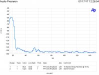
Attached are my best shots showing the forward and reverse THD of naked Vishay bulk metal 1,000 ohm resistors. 0 dB is 5 volts across the resistor under test. Using matching resistors in a bridge cancels the common mode signal and only puts under 7 mV into the AP system 2.
"For that to show anything useful you would need to ensure that the sensing lines are properly terminated in their characteristic impedance. At audio frequencies this is not resistive, and varies with frequency. You can't make an 'audio SWR bridge' just by copying an RF SWR bridge!"
There is a reason why I picked 100 ohm resistors. The RF SWR bridge technique begins to work nicely around 2,000 hertz and quite easily shows power flow direction for loudspeaker lines. Accurate and somewhat calibrated begins as low as 200,000 hertz. If I can find it I will post the FFTs from quite a while back.
Attachments

I would have started by doing two measurements, 5 minutes apart, with the same orientation.
Jan
You are welcome to try it. I did quite a number of runs under different conditions, this is the set that shows the most difference.
@simon7000:
Hi Simon ... When looking at your measurements I remember reading some time ago in an Audio Precision "news bulletin" (I think it was) that apparently metal foil resistors have some low frequency distortion that can be higher than for other resistor types. In your experience is this what is indicated in the measurement curves you show?
And regarding the orientation of the bulk foil resistors - when looking at the curves I'm thinking that they are not much different as the level differences are very low and (to my eyes) of similar character. But maybe you have a different experience as to its practical implications?
Cheers,
Jesper
Attached are my best shots showing the forward and reverse THD of naked Vishay bulk metal 1,000 ohm resistors.
Hi Simon ... When looking at your measurements I remember reading some time ago in an Audio Precision "news bulletin" (I think it was) that apparently metal foil resistors have some low frequency distortion that can be higher than for other resistor types. In your experience is this what is indicated in the measurement curves you show?
And regarding the orientation of the bulk foil resistors - when looking at the curves I'm thinking that they are not much different as the level differences are very low and (to my eyes) of similar character. But maybe you have a different experience as to its practical implications?
Cheers,
Jesper
You are welcome to try it. I did quite a number of runs under different conditions, this is the set that shows the most difference.
No Sir, YOU should have done that. Your shown curve is meaningless without baseline measurements with the same DUT orientation.
Jan
Last edited:
The sad part is that even when the "believers" are offered professional help to experimentally substantiate their claims they choose to ignore it -- I've seen it so many times and it's happening here again as we can see
Same as in homoeopathy, Bach's blossoms, and all that complementary medicinal stuff, isn't it?
There is a really cute experiment you can do. Get a 1-2 M length of copper pipe. Pass one conductor of your loudspeaker cable through it. Also pass through it two snall gauge pieces of insulated wire. Terminate one end of each smaller wire at opposite ends of the tubing. The open ends of each wire go to a 100 ohm resistor which then is connected to the tubing. Measure the voltage across each resistor while playing music. You will be able to not only see the direction of power but also the mismatch.
You will see more voltage across the resistor on the loudspeaker side. It is a simple method to show forward and reverse power.
Yes, this is a proven way, repeatable by everyone who likes (thus scientific, btw.), to determine RF power flow. But it does not prove the claim that a speaker cable works differently, depending on it's orientation.
I came to the conclusion that the OP and all the guys with some certain inclination to audiophoolery (including the BGEs) simply don't catch the physiological fact that our auditive sense is the one of our five senses with the least long term memory. Instead they replace it by a psychological phenomenon: If I alter something within my gear, it has to sound different, doesn't it? In which there's a strong correlation between the gear's alteration's costs and the amount of alteration in perception
There's still lacking a valid double-blinded study on the OP's claim, or let's say anticipation. This would be the only acceptable way to prove - or to rebut it.
Best regards!
Last edited:
TNT,
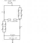
Attached is the basic resistor test. For normal testing ten resistors are used in a bridge. If the resistors are very similar, then two parts of the bridge have only half the voltage across their resistors, thus lower distortion.This process uses reciprocity to determine the distortion.
In this test only four resistors were used. The only before and after change was the direction of only one resistor.
Gentle..,
When the source of distortion is the temperature coefficient, then all resistors have increasing distortion with lower frequency. The bulk metal resistors are even worse for this. As only four resistors were used for this test, if they all had the same increase in distortion this would have cancelled. It did not showing the resistors are a bit worse for that than many others.
Jan,
????
If you look at the test shown note the excitation frequency of 18 hertz for both forward and reverse. It is the same level. As it starts at 5 volts and is down by almost 50 dB this indicates resistors all matched to within .5%
Now all the resistors are 1,000 ohms. So on the left of the metering point you have 1,000 ohms going to the generator "High" send and the same to the "Low" send allowing for the generators source resistance and the same resistances on the other side there is an effective resistance of around 1,050 ohms. This should produce a thermal noise level of around 4 nV per root hertz. This would be around -160 dB per root hertz re the 5 volt 0 dB reference. As the plot is not averaged for infinite time the noise base line is a bit higher and varies a bit. Throw in the limits of the AP System 2 and that is why the lower thermal noise limit is only around -155 dB.
Now look at the third harmonic distortion at 54 hertz. The peak levels are exactly the same. There is a slight difference at the 60 hertz line noise frequency. That is most likely due to the floor noise, as it is not likely to have any other source.
Now look at the line width spreading, some of that is the FFT limit and a bit would be to low frequency noise modulation. There doesn't seem to be much effect from the 1/F noise.
As the input signal is just under 7 mV and the useful range of the FFT system is better than 125 dB all of the data is quite reasonable.
IT SHOWS NO DIFFERENCES other than from noise. Apparently you missed DF's joke.
If someone really could hear a difference due the harmonic distortion, allowing for Fletcher-Munson giving around 200 dB selectivity, they would be much better employed by renting an office across the road from any major company boardroom and picking off stock tips!
Kay,
The directional coupler was not about measuring loudspeaker wire differences, but about the idea that power does not flow from source to load.
Attachments
Simon,
Did you evaluate also if noise spectrum changes according orientation?
Thanks
That is also shown in the FFTs. Both the same within thermal noise limits.
However what was not tested was with a non-symmetrical waveform.
The test can only prove a positive result not a negative one.
Says
Let me see if I understand this correctly and I'll crank up my gear
and do a test.
The only bulk foil resistors I have are Dale and these are low value
emitter resistors...2W .01ohm resistors.
I"ll count them and take a picture of them.
How would you like me to set them up?
place them in a bread board and do the measurements?
Then we have a 25 ohm resistors in parallel with a 100 ohm
10 turn pot? To what then should I adjust the pot to?
I might only have a larger value pot.
Jan, yes I will do two tests five minutes apart right?
one direction?
Then two other test five minutes apart the other direction right?
Then when I do the second test....isn't it done when all the resistors
have reached some level of heat saturation or stability, yes?
Now...should I tack solder the ends of the resistors except the
ones that I'm going to change direction on? is that one
or two that change direction?
Give me your guidance and I'll do it.
I will use the ShibaSoku 725D for distortion measurements.
Then I can try and do two different things after that.
From the out put I can send to a FFT a qa400.
And then I can also do a plot with a Rohde & Schwarz UPD.
I can take a pic of the screen or, I can set up a bargraph reading
that will show the values for 10 harmonics.
For either one I can use either the UPD for the signal source
or a HP339a that has a very clean oscillator output.
OH what am I to see with the two measurement points?
am I to adjust the pot to zero for the base level measurement?
Should I put a scope across those two center points?
Let me know please.
Cheers,
Sync
The trim is for nulling the excitation frequency when using lower precision resistors. It was used to test 1,000 ohm samples.
For testing resistor directivity you only need 4 resistors as well matched as possible. You must solder the resistors. I use an aluminum enclosure that has XLR connectors for inputs and outputs.
You use 10 resistors to measure the absolute distortion. Here you are looking for the relative distortion.
Using a breadboard for this test would be a good way of testing the distortion caused by the breadboard contacts. To measure something requires a bit more than hooking up a few components and reading a number off a meter. I suspect Simon spent a long time optimising his technique before he could get reliable measurements.
- Status
- This old topic is closed. If you want to reopen this topic, contact a moderator using the "Report Post" button.
- Home
- Design & Build
- Parts
- Signal direction of bulk Z-foil resistors