I understand what you are saying Lucas, but it does not fit with what is happening. That is why we are wanting you to trace what you have really done and draw it. Just putting 36V in to the whole regulator theoretically cannot give you 54V in total out. 1.414 * 36 = 51V and then losses come into play.
If you have wired things correctly it is entirely safe for you to ground the PSU as shown in the schematic.
Yes I know it's safe to ground the PSU as per the schematic. I was referring specifically to the transformer, and my questions about wiring it in series. I thought you were suggesting that I earth the central joint between the two series wired coils. Surely that is a bad idea.
I don't think I need to draw it. It's really simple. I have an 18x2 transformer. It has two primary wires, for a 240v supply (blue/brown). It has 4x secondary wires, two coils essentially, for 2 sets of 18v AC supply, and I have wired them in series by joining two together and sheathing the joint. I then use the two remaining cables as a single AC supply. That's all. But is it OK to do that? Is there a consequence of using a toroidal like that, either safety or hi-fi related, to achieve a higher voltage?
Is that clearer?
Many thanks
Lucas
Ah yes, I am feeding the 36v from the traffo (actually nearer 40v) into the + and - of the PSU, and have a wire from the centre connector direct to socket earth.
I am only using one side (+) of the PSU to get 27v DC.
Does that make sense? The phono stage sounds OK and seams very stable, so I figured all is well, mostly. I have got slightly less bass than I had hoped for, bot this is fairly subtle, and probably reflects a true RIAA set up as opposed to the bass extended version that is popular. I had a concern that it may be caused by the PSU, as I know that in power amps at least, PSU can hugely affect bass.
Is there a consensus that I should get another transformer, with higher voltage and wire the two secondaries up in parallel? Or is this not necessary?
Yes I know it's safe to ground the PSU as per the schematic. I was referring specifically to the transformer, and my questions about wiring it in series.
I thought you were suggesting that I earth the central joint between the two series wired coils. Surely that is a bad idea.
But that is exactly what the schematic shows.
There is something odd going on and I'm not sure you really understand fully what's happening. I don't think we can comment any further without seeing the thing.
OK. So I am a complete goon. It is exactly as you say. The two I wired together with shrink-wrap I've put to earth, and it didn't blow anything. The phono stage sounds much better - much more bass. Is it a surprise at all to you guys that it worked at all?
AC is a very confusing thing for me. It comes in as + and - and yet it works either way around, and yet if the live leaks to earth, it trips the RCD, but I just put one side of this seemingly reversible set-up to earth, and that's the way it stays...???!!! I just don't get it!
On the output side of the shunt reg, I can go from pins 1 to 3 and get up to 52v DC before the leds go out, but each side to centre I get 26v with leds still lit, so it all works as it should, and is within my requirements.
Thank you so much for your help and putting up with me, especially you Richie.
It's time to find a friendly electrician and ask him to explain and show you how to do this properly.AC is a very confusing thing for me. It comes in as + and - and yet it works either way around, and yet if the live leaks to earth, it trips the RCD, but I just put one side of this seemingly reversible set-up to earth, and that's the way it stays...???!!! I just don't get it!
Mains is potentially FATAL
or go down to your adult learning centre/technical college and sign up for a short course on wiring/domestic cabling/DIY electrics. or something similar.
Ask around your local to find which of your friends/acquaintances could help you out.
Thanks for your concern Andrew.
Believe it or not I've wired a whole house on my own, with two way and three way switches, 2x socket loops, 12x fuses on the consumer unit etc.
I do mostly get it. I certainly know how fatal it is. When I was younger I got a few shocks. Nothing serious, but as a consequence I am very careful these days.
Recently, building my amp and pre-amp has introduced me to a whole lot of other magic - the process by which capacitance, resistance and inductance etc. all merge to make nice music in my sitting room. That's some voodoo!
All I need now it to iron out these earthing niggles and eliminate the last remnants of hum.
I bought a 500mA Class A (+/-)Shunt Reg Kit from eBay Hong Kong, for use with an RIAA circuit I built.
The RIAA requires 2x 27v DC and pulls about 20-30mA per channel.
I can't get the shunt reg to work as I'd hoped. I have a toroidal with 18v secondaries, as recommended for the kit, and when I wire it up I get 13.7v DC per side. When I use it bipolar, of course, I get 27.4vDC, very close to my desired voltage, but I also get some small voltage fluctuations, and I can't get more than 1 volt difference with the whole range of the pots, so I don't think that's ideal at all.
I'm not sure if it is regulating properly, as I had thought I would be able to tune the voltage with the pots, and I expected absolute voltage stability.
If anybody can advise me, I would be most grateful. Here's the schematic:
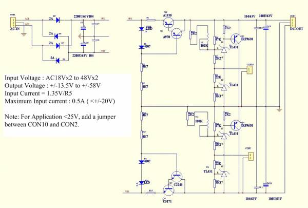
I have a use for a shunt regulator, I have seen this unit on ebay but I need 9v <500mA output but this unit only adjusts down to 13.5V. My question to someone / anyone; to get a lower voltage out is it just a matter of changing the trimpot value or is the design not suitable for my purpose?
the circuit is already modified to allow for voltages between +-13.5Vdc and +-25Vdc. See note about shorting out con1 to con2. This removes one of the voltage references (TL431) from the circuit.
You are paying for +-58Vdc capability and using just +-9V.
Go and look at Salas and Ikoflexer shunt regs.
They show a variety of circuits to suit different output voltages from 5Vdc to 300Vdc
You are paying for +-58Vdc capability and using just +-9V.
Go and look at Salas and Ikoflexer shunt regs.
They show a variety of circuits to suit different output voltages from 5Vdc to 300Vdc
- Status
- This old topic is closed. If you want to reopen this topic, contact a moderator using the "Report Post" button.
- Home
- Amplifiers
- Power Supplies
- Shunt Regulator Issues/ Questions