To be transparent the protection must allow all audio signals to pass unaltered.
That becomes a dominant requirement of any good protection scheme.
The amplifier should always pass any valid audio signal to any valid load.
If the protection scheme interferes with the audio signal when there is nothing wrong with the signal level and nothing wrong with the load, then the protection is crippling a necessary characteristic of the amplifier. Why else do we use amplifiers? I suggest to hear the music.
Now to a few questions:
What is the maximum continuous DC current that the amplifier can pass without damaging itself?
What is the maximum medium term current that the amplifier can pass without damaging itself?
What is the maximum short term current that the amplifier can pass without damaging itself?
Can a protection scheme that works well for all three of those conditions be met by one sensing system?
I would suggest very strongly that the first can be met by fusing the supply rail and/or using Dadod's suggested rail current limiter. BUT, that rail current limiter must be able to pass short term and medium term currents that are valid audio signals. Fuses will certainly meet this additional requirement.
My PS regulator is not only current limiter. It will switch off the power after certain current level. This current level is not curved in stone, for higher level the switch off will react quicker then for lover threshold. There is a loudspeaker protection too, very similar to the JLH used in his 80 W mofet amp.
dado
What about this one, a friend sugested it, it is a simulated thirystor that once activated by the current sensing devices the bjt's on both sides will keep each other on untill the power supply is turned off, one might say that is an inconvenience, you have to turn the amp off and wait for tha caps to discharge, but i don't see any problem with that, best to wait a few seconds that to loose the output devices...
This is what i am talking about, any imput would be appreciated.
This is what i am talking about, any imput would be appreciated.
An externally hosted image should be here but it was not working when we last tested it.
which part of my post are you referring back to?My PS regulator is not only current limiter.
Right now my design looking at the current going to speaker will protect the speaker from a short. I have a 70 volt power supply 5 amps and I can shorted both leads and you can see a big spark and nothing happened. Also it have a fuse and the fuse does not see it. The micro takes 20 usec to detected the short and immediately open the SSR. Belief me it is works. You can see it in the scope pictures. The good thing it is that you do not have to go into the amplifier and modify it. Juts connect the speakers output and that it is all you have to do. No every person can go into an amplifier and do some modifications.
which part of my post are you referring back to?
and/or using Dadod's suggested rail current limiter. BUT, that rail current limiter must be able to pass short term and medium term currents that are valid audio signals
I just said that is not only current limiter but it will switch the power off if certain condition are fulfilled.
dado
Listen I am using a micro. With it you can do what ever you want. You can shut down the amplifier with any abnormality you want. You can shut down the AC for high heat sink temperature, high voltage speaker output, high current in the Speaker, speaker shorts ,visual or audible alarms etc etc etc etc. I am not trying to force you to use it. I am trying to let other diyAudio members that the used of a micro can help them a lot in their design.
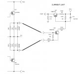
This is an example.
You sense the current in the emitter resistor to turn-on Q49.
Q49 pull down Q47 that goes on conduction.
If Q47 is powered by +Vrail, you have a 0 --> Vrail signal
If you power Q47 with +15V, you will have a 0 ---> 15V signal
Q49 will turn on with about 0.7V of Vbe. So the R161/R162 will be calculate for you rated maximum current and emitter resistor.
For example, if you want a protection at 10A, with 0.1 emitter resistor, it will be a 2V dropout on AB points.
So, to reduce 2V to 0.7V you've to calculate R161 and R162. If you get R161 in fixed value (for example, as the draw, 470ohm) the formula is:
0.7V = 2V * R162 / ( R162+R161)
so you have to invert the formula to have R162 =
for multiple output transistor, the schema is similar but the current sense is made in each complementary pair (in my schema there's only 1 complementary pair) via 22ohm resistor.
1000W at 4ohm are 15.8A (i think that the 1000W are RMS, so current is RMS). 15.8Arms are 22-23A peak.
So, for 12 pairs you've to divide by 12, so less that 2A each pair.
2A in 0.47ohm resistor create a voltage drop of 0,94V.
So you've to reduce, with R162, the voltage from 0,94V to 0,65-0,7V
..and you've an overcurrent protection.
The transistor (Q49) will start to turn on when it's Vbe rises to ~ 400mVbe.
That turn on point should not interfere with the passing of a valid audio signal.
If it turns on earlier than not interfering with a valid audio signal then you are not passing the music you are supposed to hear. The current limiter has then failed in it's primary purpose - to let you hear the music.
To stop you blowing up the amplifier is not the primary purpose. Otherwise you could simply never turn the amplifier on. Music is the primary purpose.
Which 400W amp? Protection circuits are either an integral part of the power amp (limiters) or are a carefully matched temperature/current limit circuit that should also senses DC at the output, delay the speaker connection to prevent thumps and shut off the load when something is amiss. Quite a lot!
Any protection circuit has to be calculated with the amplifier specification and operating conditions known. Unfortunately, many people are unaware of what they really have, believing they have built or bought massively powerful amplifiers only to discover that was just sales talk or depended on their power supply, number of output transistors, brand and quality of parts etc.
Any protection circuit has to be calculated with the amplifier specification and operating conditions known. Unfortunately, many people are unaware of what they really have, believing they have built or bought massively powerful amplifiers only to discover that was just sales talk or depended on their power supply, number of output transistors, brand and quality of parts etc.
Has anyone tried looking into sensing the current in the rails before the amp instead of the common method at the emitter resistors?
A very small value resistor on each rail (smaller than the common emitter res values used) could sense abnormal current, which would clearly indicate a short condition or an overly low impedance load driven hard.
And this would not interfere with the amp's sound reproduction.
To allow for fast transients to still make it through without tripping anything, a designed-in reaction delay can be implemented.
Perhaps with such a sensing system, 2 different thresholds could be used, the first would only cause limiting of the input drive level, and when this is insufficient, the second level could cause a mute with load disconnect.
This could be coupled with a sink temperature sensing, which could be causing the same muting/disconnect actions.
The actions taken don't even have to latch and wait for user "reboot", as there can also be a delay applied and automatic return to normal. If the conditions causing the trip are still present, then return to normal would have to wait longer, until the fault is cleared.
Has anyone tried looking into sensing the current in the rails before the amp instead of the common method at the emitter resistors?
yes, Apex used 0.1 sensing resistors, it is posted here, just cant remember which thread
you can pm him dsirectly, i will try to find the links...
It's very simple to made.
Look on this picture please.
An externally hosted image should be here but it was not working when we last tested it.
Resistors R3 and R4 are in function of the shortcut protection. If you take some Ohms (Ohm or two, depend on amplifer capability for low Ohms load (loadspeakers). In this case amplifier loads (in shortcut position) something similar like we have loudspeaker on it (with no shortcut). But usualy more than 1 Ohm is needed
Thats clearly the simplest way to protect your circuit. But this is only shortcut protection, not DC, with no delay function,...
i cant see your protection circuit diagram
Softvare is Multisim 2001 supported with Corel Photo paint, Corel Draw, Photoshop and sometimes with 3D studio MAX and Solid Works (not in this case).
Please be careful with this schematic. It is only an idea. I do this in a few minutes, but isn't exist in the real life.
Circuit based on some old aplication from Motorola, with two Darlingtons on the Out, BCs, but they are (BCs) to devide 30V of supply voltage into 15V (resistor devider) what is OK for most OPamps, because in original shematic, you have only darlingtons on out, BCs and OPamp (opamp is a driver which drives output transistors with supply curent).
All of those driver options are only substitute for OP AMP. If you want to made something on higher voltage, need to be careful on resistor devide relation on resistors with BCs.
Other infos (FETs, BC substitutes,...), I'll post later.
hello .. i cant see the schematic can you please send it again the short circuit protection
- Status
- This old topic is closed. If you want to reopen this topic, contact a moderator using the "Report Post" button.
- Home
- Amplifiers
- Solid State
- short circuit protection